


12
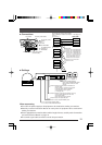
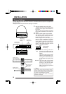
50 100 170 180 300 320 500
0.65 0.9 1.2 1.6 2.0
1.25 2.0
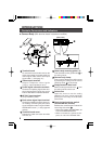
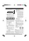
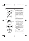
Connections to Terminal Board
Turn OFF the power supply to all equipment
to be used before making connections.
Connections to Terminal Board
Remove the terminal board cover and
connect the video signal cable (coaxial
cable) (
×
1). Connect the AC 24V power
cables (
×
2) and the control signal cables (
×
4).
When alarm input via the camera is used,
connect the alarm input cables (
×
2) to the
panic alarm signal input terminals.
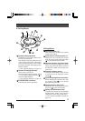
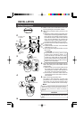
Ⅵ AC 24V power supply cable
Connect the AC 24V power supply to the
AC 24V terminals on the terminal board.
To prevent connection errors or a cable
disconnection, we recommend the use of
lug plates for the connections.
The following table shows the connection
distances.
Maximum extension (m)
CPEV, VVF, etc.
conductor diameter (mm)
CCV, etc. conductor
cross section (mm
2
)
INSTALLATION
Lug plates
AC 24V power cable
To AC 24V power supply
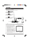
RM-P2580
Video signal
cable (coaxial
cable)
Remove the terminal board cover
by flipping it up while pushing its
top to the left.
Control signal cable
or place the power supply near to the
camera. If voltage drop occurs during
operation, the performance will be
unstable.
• Be sure not to inadvertently connect the
AC 24V cable to an AC 120V power
supply. This could destroy the unit.
To switcher,
monitor, Remote
Control Unit RM-
P2580
Terminal board
CAUTION:
• If thin cables are used (i.e. with a high
resistance), a significant voltage drop
will occur when the unit is at its
maximum power consumption (pan, tilt,
zoom operated simultaneously). Either
use a thick cable to restrict the voltage
drop at the camera side to below 10%,