


14
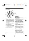
Camera Settings
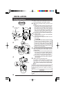
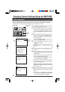
1.
Open the switch cover on the side.
To open the cover, pull outward while
pressing at the edge in the direction of
the arrow.
(Be sure not to press with excessive
force as this could deform or destroy the
cover.)
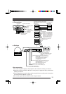
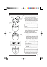
2.
Set the control signal selector switch.
This switch is used to switch the input
and output signal to and from the con-
trol signal connection terminals.
When shipped from the factory, the
switch is set to “422A/485”. Normally,
there should be no need to change this
setting. When it becomes necessary to
change the setting, use a fine screw-
driver or other difficult to break or bend
object to change the setting.
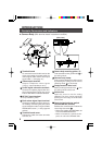
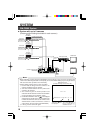
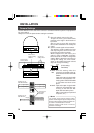
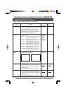
INSTALLATION
Set the switches on the side of the camera in accordance with the system or equipment to
be connected to.
Always turn OFF the power before setting the switches.
Switch cover
Press.
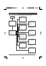
Camera ID
setting switch
System setting
switches
Control signal
selector switch
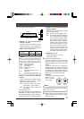
Settings for use
with RS-422A/485
Settings for use
with RS-232C
RXD (signal input)
GND (signal GND)
TXD(signal output)
Control signal
connection
terminals
RX– (– signal input)
RX+ (+ signal input)
TX– (– signal output)
TX+ (+ signal output)
232C
422A
485
(Initial setting:
422A/485)
● 422A: Use this setting when the
485 camera is connected to the op-
tional Remote Control Unit RM-
P2580.
Input and output of signals with
electrical characteristics con-
forming to the EIA/TIA RS-422A
or RS-485 standard takes
place.
● 232C: Input and output of signals with
electrical characteristics con-
forming to the EIA/TIA RS-
232C standard takes place.
(When connecting to a personal
computer, etc.)
Memo:
The control signal selector switch setting
position and the signals input and output to and
from the control signal connection terminals are
as shown in the illustration on the left.
Improper setting could result in incorrect
operation or damage.
Empty