


9
12
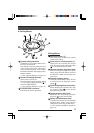
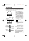
System setting switches
Set switches in accordance with the sys-
tem to be connected to.
The settings comprise setting the form
of the control signal cable connection,
communication protocol, control signal
termination ON/OFF, and image synchro-
nization method.
(੬ See “Camera Settings” on page 14.)
13
Camera ID setting switches
Use to set the camera ID.
Be sure to set the camera ID when switch
1 of the system setting switches
12
is
set to ON (MULTIDROP).
(੬ See “Camera Settings” on page 14.)
14
FOR SERVICE connector
Exclusively for service purposes.
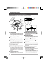
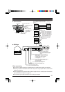
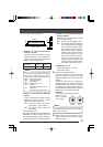
Ceiling Mount
15
Mounting holes (
×
4)
Use these holes to attach the ceiling
mount to the ceiling.
16
Guide holes for mounting camera (
×
3)
Guide holes for mounting the camera
body. The camera body mounting guides
7
are inserted into these holes.
17
Camera direction alignment mark
When mounting the ceiling mount to the
ceiling, align this mark with the center of
the direction in which you want the cam-
era to face.
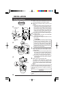
18
Camera clamping screw
To hold the camera body in place, be sure
to use this screw to clamp the camera
clamp
8
.
19
Positioning alignment protrusion
When attaching the camera body, align
the camera clamp
8
on the camera
body with this protrusion.
20
Drop prevention wire hook
Attach this wire to the drop prevention
wire hook
9
on the camera body.
21
Safety wire attachment hole
To prevent the camera from accidentally
dropping down, fasten a wire from the
ceiling to this hole using an M3 screw.
(੬ See “Ceiling Installation” step
2.
on
page 16.)
Ⅲ Ceiling Mount
21
%
%
*
^
)
&
^
%
^
%
(