


32
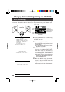
PANIC ALARM
By inputting an alarm signal through the panic alarm signal input terminal (੬ See page
13.), a specified position can be invoked from which surveillance is then conducted.
The camera can be set so that the PANIC ALARM operation overrides manual operation,
AUTO PATROL operation and AUTO PATROL operation by terminating these. By installing a
switch near the camera, a single press in an emergency situation will effect immediate
observation of an important surveillance point.
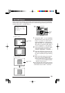
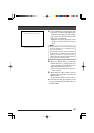
1.
Connecting the Alarm Signal (੬ See page 13.)
● Supply a no-voltage contact signal to the panic
alarm signal input terminal.
Be sure not to supply voltage or connect to other
apparatus (open collector terminal, etc.).
This could result in incorrect operation or damage.
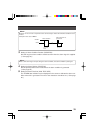
● By linking multiple contacts (switches), as
shown in the illustration, the alarm condition
can be activated when any of the contacts
comes on.
Memo:
Ensure that the maximum line resistance value
becomes 100 Ω or less inside the alarm circuit
(ALARM IN1 ~ alarm generating switch ~ ALARM
IN2). If the resistance is large, the alarm may not
work correctly.
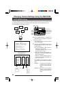
When the contact closes (short), the alarm condition is
generated:
When the contact opens (open), the alarm condition is
generated:
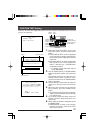
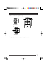
2.
Setting of Alarm Signal Polarity (POLARITY)
Match the setting with that of the alarm generating contact (switch). (੬ See page 24.)
Set to MAKE.
Set to BREAK.
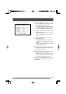
ALARM 1
OTHERS
ALARM 2