


16
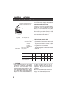
Camera
direc-
tion
mark
3 mm
or
less.
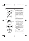
Ceiling Installation
INSTALLATION
75
mm
1.
Drop prevention
wire
Hook
4.
Guide
Tab
Connector
cable
Tab
Guide
3.
Connector
on terminal
board
3.
-1)
3.
-1)
3.
-2)
2.
White wire
To ceiling slab
or channel
M3 screw
Wire
Safety wire
attachment
hole
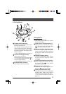
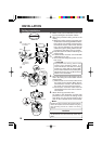
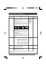
Memo:
Bundling the drop prevention wire together with the
cables connected to the terminal board using vinyl
tape will help prevent the cables from being
pinched.
CAUTION
Be sure to attach the drop prevention wire. If
not attached, the camera body could drop
down.
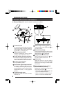
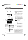
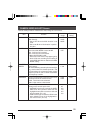
1.
Make a hole (75 mm diameter) in the ceil-
ing for passing the connection cables.
2.
Attach the provided ceiling mount to the
ceiling.
● Attach the ceiling mount so that the cam-
era direction mark is aligned with the direc-
tion in which you want the camera to face.
Coincide the center of the mount with the
hole (75 mm diameter) for passing the
cables through the ceiling. Attach the ceil-
ing mount to the ceiling using 4 screws.
● Use M4 screws or bolts for attaching the
ceiling mount.
● If wood screws are used, use screws with
a diameter of 4.1 mm.
● The screw head height should be no more
than 3 mm.
CAUTION:
To prevent the ceiling mount and
camera from dropping down, it is
recommended to connect the ceiling
mount to a ceiling slab or channel with
a wire. Fasten the wire to the safety wire
attachment hole using an M3 screw as
shown in the illustration.
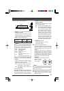
3.
Pass the wired terminal board through the
hole in the ceiling mount and attach it to the
camera body.
1) Slide the tab on the terminal board into
the guide on the camera. When the ter-
minal board is moved in the direction of
the arrow, it is secured to the camera.
2) Connect the connector cable from the
camera body to the connector on the ter-
minal board.
4.
Attach the drop prevention wire.
As shown in the illustration, pull the drop
prevention wire out from the ceiling mount
and attach it to the drop prevention wire
hook on the underside of the camera body.