


8
1
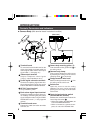
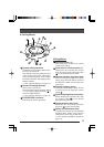
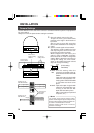
Terminal board
To connect the coaxial cable used as the
video signal cable, the power cable, the
control signal cable, and the alarm input
signal cable. (੬ See page 12.)
2
Video output terminal
Outputs composite video signals
(1V(p-p), output impedance 75 Ω).
3
Control signal connection terminals
Terminals for inputting signals with elec-
trical characteristics conforming to the
EIA/TIA RS-422A or RS-485 standard.
4
AC 24 V input terminal
To input AC 24 V power.
5
Panic alarm signal input terminal
Terminal for inputting the panic alarm sig-
nal. Settings concerning the panic alarm
signal should be made using the PANIC
ALARM SET screen. (੬ See pages 24
and 32.)
6
Terminal board cover
Protects the cable connection terminals
from dirt, etc.
7
Camera body mounting guides (×3)
To be inserted into the guide holes
16
of
the ceiling mount.
8
Camera body clamp
Fix the camera body to the ceiling mount
by fastening the ceiling mount’s camera
clamping screw
18
to this clamp.
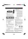
9
Drop prevention wire hook
Attach the drop prevention wire
20
from
the ceiling mount to this hook.
10
Switch cover
Open this cover to use the setting
switches. The cover can be opened by
pushing the cover edge in the direction
of the arrow.
11
Control signal selector switch
(RS-422A/RS-485, RS-232C)
Switches the communication mode of the
control signal terminal
3
.
• When connected to the RM-P2580, set
to the RS-422A/RS-485 side.
• When connected to a personal com-
puter, etc. set to the RS-232C side.
Controls, Connectors and Indicators
Ⅲ Camera Body (With terminal board in attached condition)
INTRODUCTION
(Side view)
7
6
9
2
7
7
3
5
4
1
8
0
$
#@!