


Cintel International Ltd. diTTo User Guide
Issue 3 5
Installation
System set-up
Ensure the ac mains supply has been fully disconnected prior to removing any cover plates. This task must be
performed only by suitably qualified personnel.
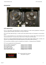
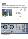
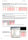
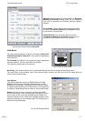
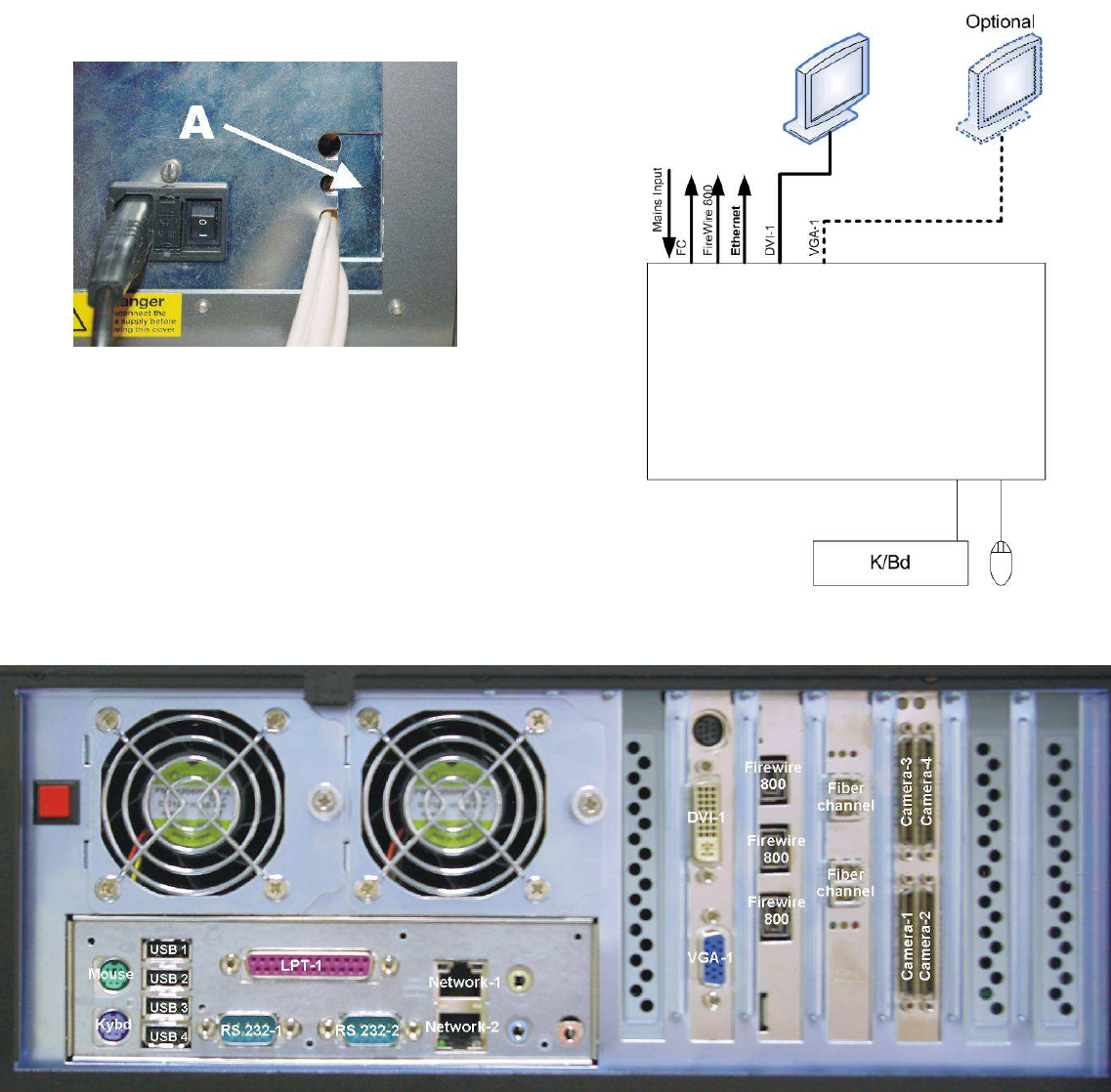
Connections to the scanner are via an EMC gland plate located at rear of the scanner. Remove the 4 screws (4 x M3)
that hold the small adjustable aperture plate, Fig 1(A), feed through the appropriate cable to the diTTo internal PC.
Further access can be gained by removal of the side vent plates (6 x M6).
Fig 1 EMC Gland
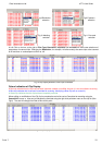
Fig 2 External Connections to diTTo PC
Fig 3 Internal connectors of diTTo PC
diTTo
Scanner