


21
Leica SP2600 Ultramilling attachment
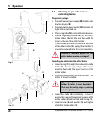
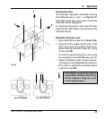
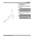
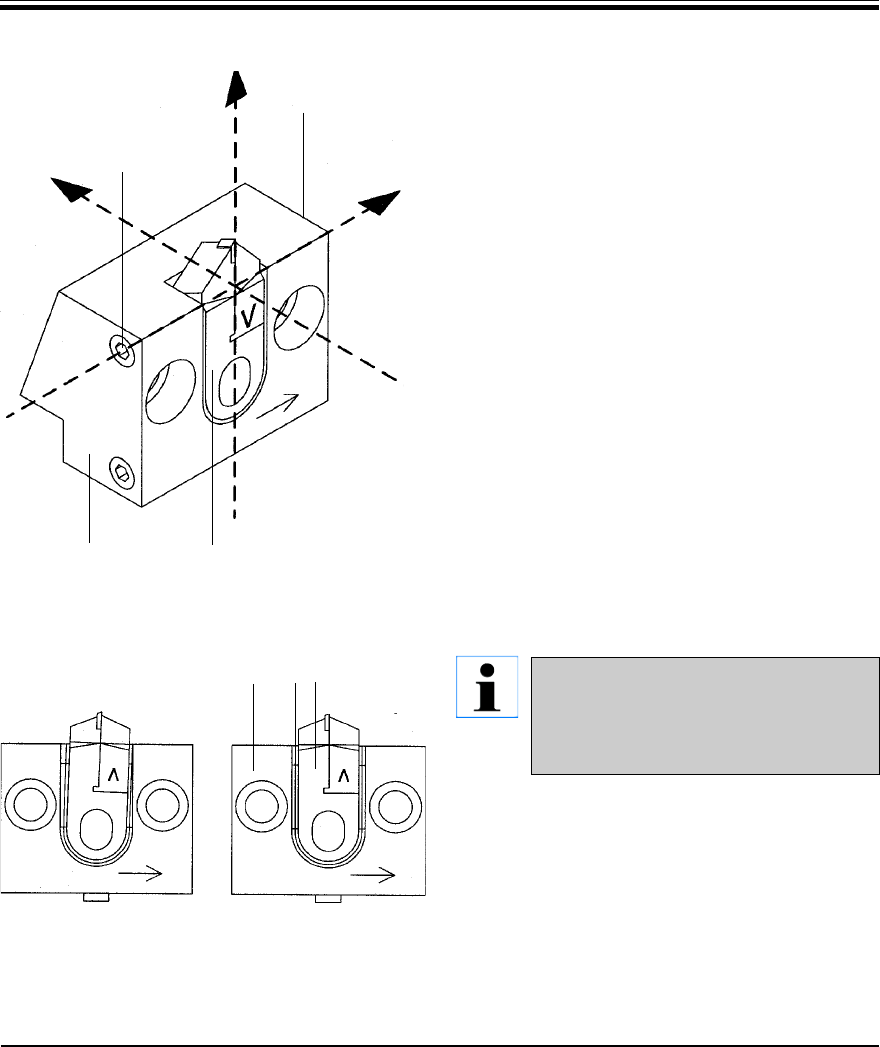
Adjusting the miller
The miller (3) is adjusted in the holder (2) along
three different axis (x, y and z - see Fig. 5.3, left).
Adjustment along the x-axis is done outside the
calibration device (18, Fig. 5.1).
For adjustment along the z- and y-axis, the miller
holder (2) with miller (3) has to be fastened in the
calibration device.
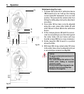
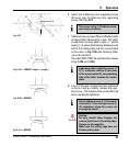
Adjustment along the x-axis
Adjust miller (3) as shown in Fig. (5.4a / 5.4b).
Along the entire length of both sides of the
miller, there must be a uniform distance be-
tween miller (3) and miller holder (2) / spring
(1) (see Fig. 5.4b).
The miller is adjusted along the x-axis via the
two regulating screws (6) (Allen key, size 2.5).
Tighten (clockwise) and/or loosen (counter-
clockwise) screws (6, Fig. 5.3) alternately un-
til the miller is adjusted to a parallel position
as shown in Fig. 5.4b.
Do not tighten screws (6) too much. If
screws (6) are too tight, screw (7, Fig.
5.2) (for adjustment along the y-axis)
can no longer be moved.
Fig. 5.3
5. Operation
X
2
3
6
6
Z
Y
Fig. 5.4a: WRONG Fig. 5.4b: CORRECT
132