


22
Supplementary instruction manual V 1.2 07/2002
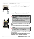
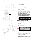
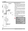
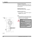
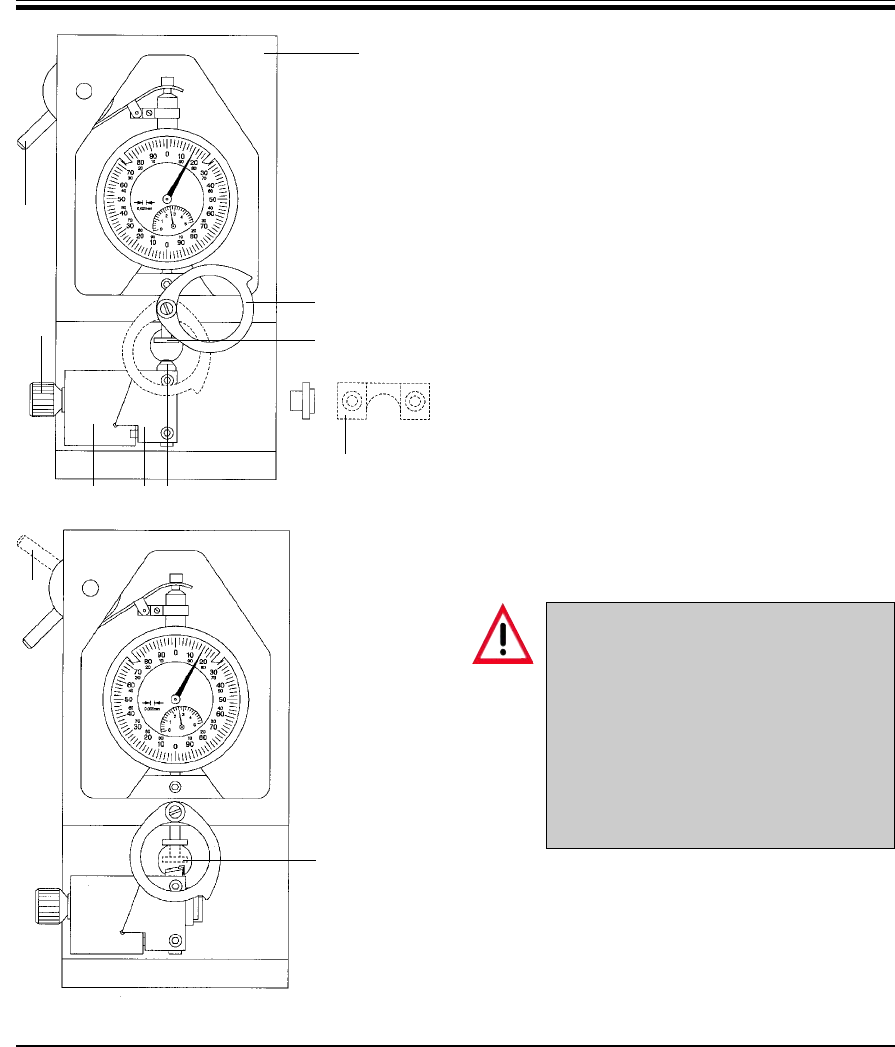
Adjustment along the z-axis
1. Pull lever (12) at the left of calibration device
(18) forward as far as it will go, thus moving
contact plate (17) backwards to its rear limit
position. This prevents the contact plate from
hitting the milling edge during the adjustment
procedure.
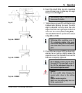
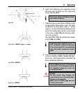
2. Once miller (3) has been correctly adjusted
along the x-axis, place miller holder (2) with
miller (3) next to block (8) into the calibration
device.
3. Fit the clamping device (9) (with the semicir-
cular recess pointing in your direction) against
the miller holder (2) and fasten with two
knurled screws (10) (turn screws clockwise).
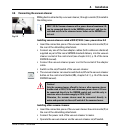
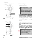
4. Rotate magnifier (16) forward to a position
above the miller.
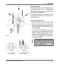
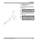
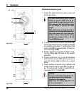
5. With lever (12), bring contact plate (17) close
to the miller (move lever backwards) until just
a very small gap remains (see Fig. 5.6).
Caution:
The gauge contact plate must never hit
the milling edge.
This could damage the surface of the
contact plate, leading to incorrect
measuring results.
Be very careful when bringing the con-
tact plate close to the milling edge.
Always use the magnifier.
Fig. 5.5
18
12
2 38
9
10
16
17
Fig. 5.6
(12)
17
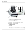
5. Operation