


40
Supplementary instruction manual V 1.2 07/2002
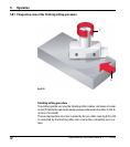
5.8 Finishing milling
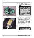
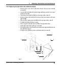
Attach the miller holder containing the finishing miller to the milling
spindle (Allen screws / Allen key size 5) - see Fig. 5.21, page 34).
Always slide the plexiglass cover to the upper limit position prior
to attaching the miller holders to the milling spindle!
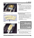
Bring the cutting edge of the miller close to the specimen surface and
thoroughly check the distance between miller cutting edge and speci-
men surface as described for the pre-miller on page 35.
If necessary, adjust the milling window (button (61) and others - see
chapter 5.4.14, page 37 of Leica SM2500 instruction manual).
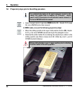
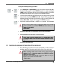
Setting the milling parameters for the finishing milling procedure
Once again activate automatic mode of operation AUTO and set the
milling parameters using the same control unit buttons as described for
the pre-miller on page 36.
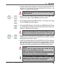
Individual parameter settings depend on specimen material and
size. Please refer to the recommendations below and on the fol-
lowing page.
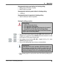
Recommended milling thickness settings for finishing milling
5 µm - keep milling until surface is completely level.
3 µm - three entire sledge strokes (milling and return stroke).
2 µm - three entire sledge strokes (milling and return stroke).
1 µm - three entire sledge strokes (milling and return stroke).
Do not exceed a milling thickness setting of 5 µm with the follow-
ing materials: brittle, very ductile materials such as titanium or fi-
berglass and compound samples containing such materials (such
as printed circuit boards).
5. Operation