


23
Leica SP2600 Ultramilling attachment
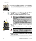
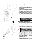
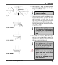
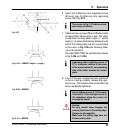
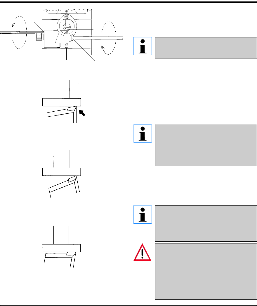
6. Insert the size-5 Allen key into regulating
screw (4) insert size-2.5 Allen key into regu-
lating screw (11) (Fig. 5.7).
The arrows in Fig. 5.7 indicate clock-
wise sense of rotation.
7. Tighten/loosen screws (11) and (4) alternately
to adjust miller (3) along the z-axis. The miller
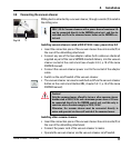
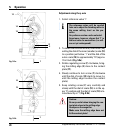
edge is adjusted correctly when the outer
edge of the miller is at right angles to the front
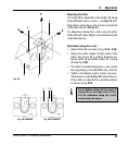
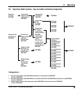
surface of the contact plate (see Fig. 5.8a).
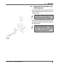
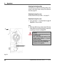
The miller MUST NOT be positioned as shown
in Fig. 5.8b and 5.8c!
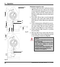
Tightening either regulating screw (4,
11) (= clockwise rotation in the sense
of the arrow) brings the corresponding
side of the miller closer to the contact
plate.
8. If one of the two screws (4, 11) has been tight-
ened as far as it will go, slightly release the
opposite screw. This slackens the screw that
had been completely tightened .
Do not tighten screws (4, 11) too much.
If screws (4, 11) are too tight, screw (7,
Fig. 5.2) (for adjustment along the y-
axis) can no longer be moved.
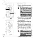
Caution:
Be very careful when bringing the
contact plate close to the milling
edge.
Always use the magnifier.
Make sure the milling edge does not
hit the contact plate!
Fig. 5.8 b - WRONG
Fig. 5.8 a - CORRECT
5. Operation
Fig. 5.7 4
11
3
7
Fig. 5.8 c - WRONG
90°