


VPort 2310 User’s Manual Introduction
1-5
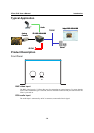
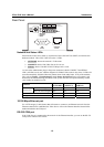
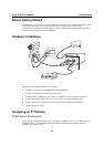
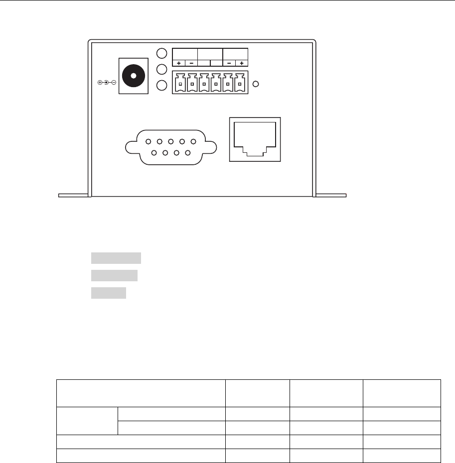
Rear Panel
COM
(RS-232)
10/100 Mbps
Ethernet
1: NETWORK
2: CONNECT
3: SERIAL
1
2
3
INPUT
12 VDC
RESET
COM
RS-485
Relay
Output
Digtal
Input
NO
C
C: Common
NO: Normal Open
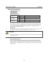
Network and Status LEDs
Each time the Video Server starts up, it performs a Power-On-Self-Test (POST) to examine each
hardware module. VPort 2310 Video Server has 3 LEDs:
1. NETWORK: detects the network’s Tx/Rx status
2. CONNECT: checks if the Video Server alive or not
3. SERIAL: checks if the RS-232/485 COM port alive or not
As soon as the administrator plugs in the power connector, both the CONNECT and SERIAL
LED’s will flash, one by one, until the diagnosis is finished. If the result is okay, these 2 LEDs will
turn off momentarily, and then follow the pattern shown in the table below. If any of the modules
fails, refer to Chapter 7, Troubleshooting, under Power On Self Test for the error pattern, and
then follow the troubleshooting procedures. If the system still does not operate normally, contact
your reseller for technical service.
Condition
LED1
(NETWORK)
LED2
(CONNECT)
LED3
(SERIAL)
VPort’s IP is assigned Flash Flash OFF
Ethernet alive
VPort’s IP is not assigned Flash OFF OFF
Ethernet defunct OFF OFF ON after 30 sec
During camera control Flash Flash Flash
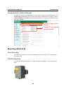
10/100 Mbps Ethernet port
Use a UTP category 5 cable shorter than 100 meters to connect to an Ethernet network. Once the
Ethernet connection is established, the Video Server will use the Ethernet interface instead of the
modem attached to the COM port.
RS-232 COM port
If the Video Server is connected to the network via the Ethernet interface, you can use the RS-232
serial port to control a PTZ camera.