


VPort 2310 User’s Manual System Configuration
4-16
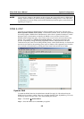
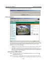
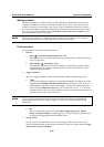
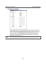
Weekly schedule
The Weekly schedule is provided for daily security applications. Administrators can select any
weekday from Monday to Friday with the daily schedule set from 9 am to 6 pm when no one is
available to perform event checking. If the security system is installed in an office for which no
one is present on nights or weekends, administrators can still set the time period as above, from 9
am to 6 pm. However, remember to select All the time except for the above schedule to let the
program run during nights and weekends.
NOTE
Either “Weekly schedule” or “All the time except for the above schedule” must be selected, or
the applications described in the following sections will not work properly.
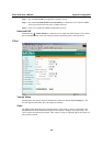
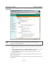
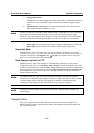
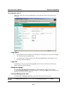
Event operation
Event operation is for setting security applications.
1. General
a. Delay □ seconds before detecting the next event:
The administrator can set up the time interval (in seconds, from 0 to 999) between each
event’s trigger action.
b. Take snapshot □ seconds after event:
The alarm message transmitted via FTP or Email is accompanied by snapshot images.
The administrator can set how much time (from 0 to 999 sec)to wait after an event is
triggered to take the snapshot.
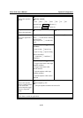
2. Trigger Condition
There are 2 trigger conditions: Video Motion Detection (VMD) and Digital Input (DI)
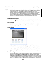
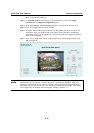
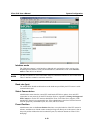
a. VMD:
To set up the VMD trigger condition, the administrator should first configure the VMD
condition on the Configuration/Motion Detection page (refer to the “How to set up a
VMD condition” subsection earlier in this chapter), or click on the Motion Detection
link to link to the Motion Detection page. You are allowed to set up 1, 2, or 3 motion
detection windows. After you name a window, the name you selected will appear on the
Application page, below “detect motion in:”
NOTE
VPort’s Network and Status LEDs can be used to determine if the VPort is transmitting and
receiving data over the network. Refer to Chapter 1 to see how to interpret the Network and
Status LEDs.
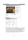
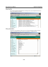
b. DI:
There are 4 Digit Input statuses, including Input is High, Input is Low, Input is
Rising, and Input is Falling. An edge trigger (e.g., Rising or Falling) is generally used
to detect the emerging signal from the external sensor.
3. Trigger Action
Once an event occurs, administrators can set up the trigger action after the event occurs
and/or send snapshots that are taken right at the moment. There are 2 trigger actions: Trigger
output alarm and Upload snapshot