


VPort 2310 User’s Manual Introduction
1-6
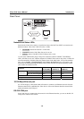
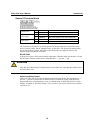
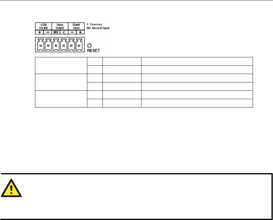
General I/O terminal block
+ Data+
COM RS-485
- Data-
NO Normal Open Max. 1A, 24 VDC or 0.5A, 125 VAC
Relay Output
C COMMON Short with Normal Close at the initial state
- DI-
Digital Input
+ DI+ Max. 50 mA, 12 VDC
The Video Server provides a very flexible general I/O interface that can be used with security
devices, such as sensors, alarms, lighting fixtures, or door locks. The general I/O terminal block
has six pins for device control. These pins can be divided into two categories based on the
interface being used (RS-485 or DI/DO).
RS-485 COM
If the device (such as a PTZ camera control) connected to COM has an RS-485 interface, wire the
RS-485 Data+ and Data- control lines to COM RS-485’s “+” pin and “ –” pin.
ATTENTION
Since RS-485 COM and RS-232 COM share the same UART chip, either RS-485 or RS-232 (but
not both) can be used.
Digital Input/Relay Output
VPort 2310 Video Server provides one digital input and one relay output. The Digital Input’s “+”
pin and “-” pin can be connected to an external sensor to monitor the voltage according to the
programmed scripts in configuration (see the “Command Script for DI/DO & Camera’s Actions
Setting” in Chapter 5). The Relay Output’s “NO” pin and “C” pin can be used to turn an external
alarm on or off.