


2
X
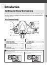
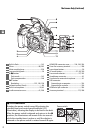
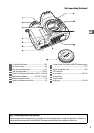
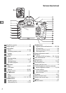
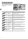
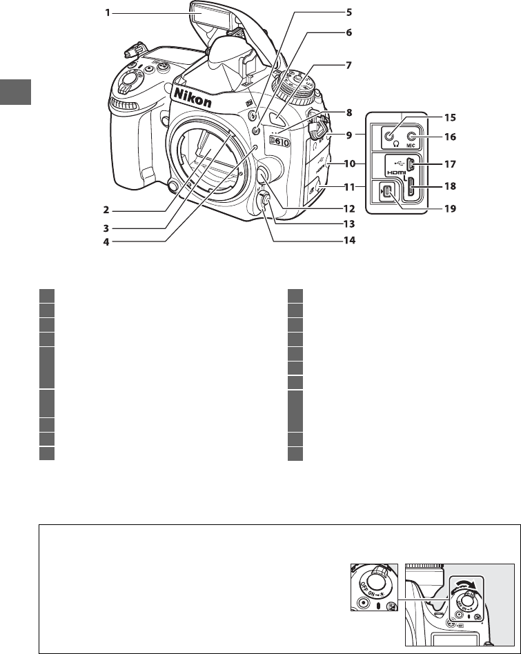
The Camera Body (Continued)
1 Built-in flash..........................................................143
2 Mirror...............................................................88, 303
3 Meter coupling lever...........................................328
4 Lens mounting mark.............................................26
5 M/Y button
Flash mode........................................................143
Flash compensation........................................148
6 D button
Bracketing........................................153, 156, 158
7 Infrared receiver (front)........................................86
8 Built-in microphone....................................... 58, 65
9 Audio connector cover................................61, 298
10 HDMI/USB connector cover............194, 196, 204
11 Cover for accessory terminal ............................298
12 Lens release button...............................................26
13 AF-mode button.....................................51, 98, 100
14 Focus-mode selector ................................... 97, 103
15 Headphone connector......................................... 61
16 Connector for external microphone................. 61
17 USB connector
Connecting to a computer............................194
Connecting to a printer..................................196
18 HDMI mini-pin connector..................................204
19 Accessory terminal.....................................175, 298
A LCD Illuminators
Rotating the power switch toward
D
activates the
standby timer and control panel backlight (LCD
illuminator), allowing the display to be read in the dark.
After the power switch is released and returns to the ON
position, the illuminators will remain lit for six seconds
while the standby timer is active or until the shutter is
released or the power switch is rotated toward
D
again.
Power switch