


PC Configuration
13
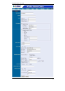
Click on ASCII or HEX check box to select input format as ASCII format or HEX
format, and then input WEP key. To Confirm the WEP key you must enter the data
once again in the Confirm WEP Key field.
ASCII input format:
ASCII format causes each character to be interpreted as an eight-bit value. All
unaccented upper- and lower-case Western European characters that can be
input through your keyboard's typing zone are valid. To setup 64-bit WEP key,
input 5 ASCII characters, for example, ‘12345’. To setup 128-bit WEP key, input
13 ASCII characters, for example, ‘1234567890123’. These character counts
result in bit counts of 40 and 104, respectively; ICA-100W will automatically pad
your input to a bit count of 64 or 128.
HEX input format:
Hex format causes each pair of characters you type to be interpreted as an
eight-bit value in hexadecimal (base 16) notation. Only the digits 0 through 9 and
the letters A through F (in upper or lower case) are valid. To setup 64-bit WEP
key, input 10 HEX format, for example, ‘3132333435’, this is the same with
ASCII input ‘12345’. To setup 128-bit WEP key, input 26 HEX format, for exam-
ple, ‘31323334353637383930313233’, this is the same with ASCII input
‘1234567890123’. These character counts result in bit counts of 40 and 104, re-
spectively; ICA-100W will automatically pad your input to a bit count of 64 or 128.
On the Confirm WEP Key field, input the same characters as the Encryption
Code field. Make sure the Encryption Code is the same with the access point’s
encryption code that ICA-100W is to be connected under Infrastructure mode.
Your PC/Notebook’s encryption code also needs to be setup the same with ICA-
100W's encryption code under either Infrastructure mode or Ad-hoc mode.
The default setting for the Encryption Key is Disable therefore, to secure the
wireless transmission be sure to Enable the Encryption Key by entering the rele-
vant data.
Note: Carefully input Encryption Code, any error setting will cause communica-
tion link to fail.
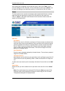
LED Control:
The LED control allows user to setup the LED illumination as desired. This feature
provides the flexibility when surveillance activity is ON.
There are three options as follows:
Normal
Power - Steady On of the LED indicator.
LAN - Steady On of the LED indicator. When LAN activity is present the LED indica-
tor will flash steadily.
OFF
Power - LED indicator is off
LAN - LED indicator is off
Dummy
Power - Steady On of the LED indicator.
LAN - Steady On of the LED indicator with random flashing.
The default setting for the LED control is at Normal. When you have configured the
LED control the correct illumination will set in after 1 minute.