


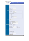
Broadband Router User Guide
4
begins to light up, then release the reset button and the Power LED will begin to flash
indicating ICA-100 is changing to factory reset. When factory reset is completed the IP
address will return to the default setting as 192.168.0.20.
Factory Reset of ICA-100W: Press the reset button for three seconds or until Power
LED begins to light up, then release the reset button and the Power LED will begin to
flash indicating ICA-100W is changing to factory reset. When factory reset is com-
pleted ICA-100W will be set to default on channel 11 and EES-ID is set as “NULL
String” (This default setting will let ICA-100W able to connect ANY access point on the
infrastructure network). The IP address will also return to the default setting as
192.168.0.20.
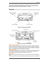
I/O Connector
There are four I/O connectors, two for input and two for output situated on the rear
panel. The I/O connectors provide the physical interface to send and receive digital
signals to a variety of external alarm devices. Please refer to the User’s Guide appen-
dix for detailed information.
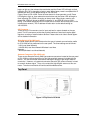
Slide Switch( ICA-100W only)
The slide switch permits user to determine the type of network communication media
for ICA-100W and is positioned on the rear panel. The three settings are as follows:
· LAN (Local Area Network)
· LAN/WLAN (Local Area Network/Wireless Local Area
Network)
· WLAN (Wireless Local Area Network)
Antenna Connector( ICA-100W only)
There are two Reverse Polarity SMA type antenna connectors located at the rear panel
of ICA-100W providing connection for two high sensitivity antenna included with the
device. You can also install the antenna with higher dB gain to get longer distance
connection. However, only antenna connector above the DC power connector is used
to transmit wireless signal. Thus, only connect the high dB gain antenna to this con-
nector. The other one should still connect with bundled antenna.
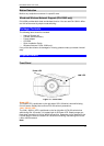
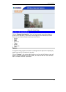
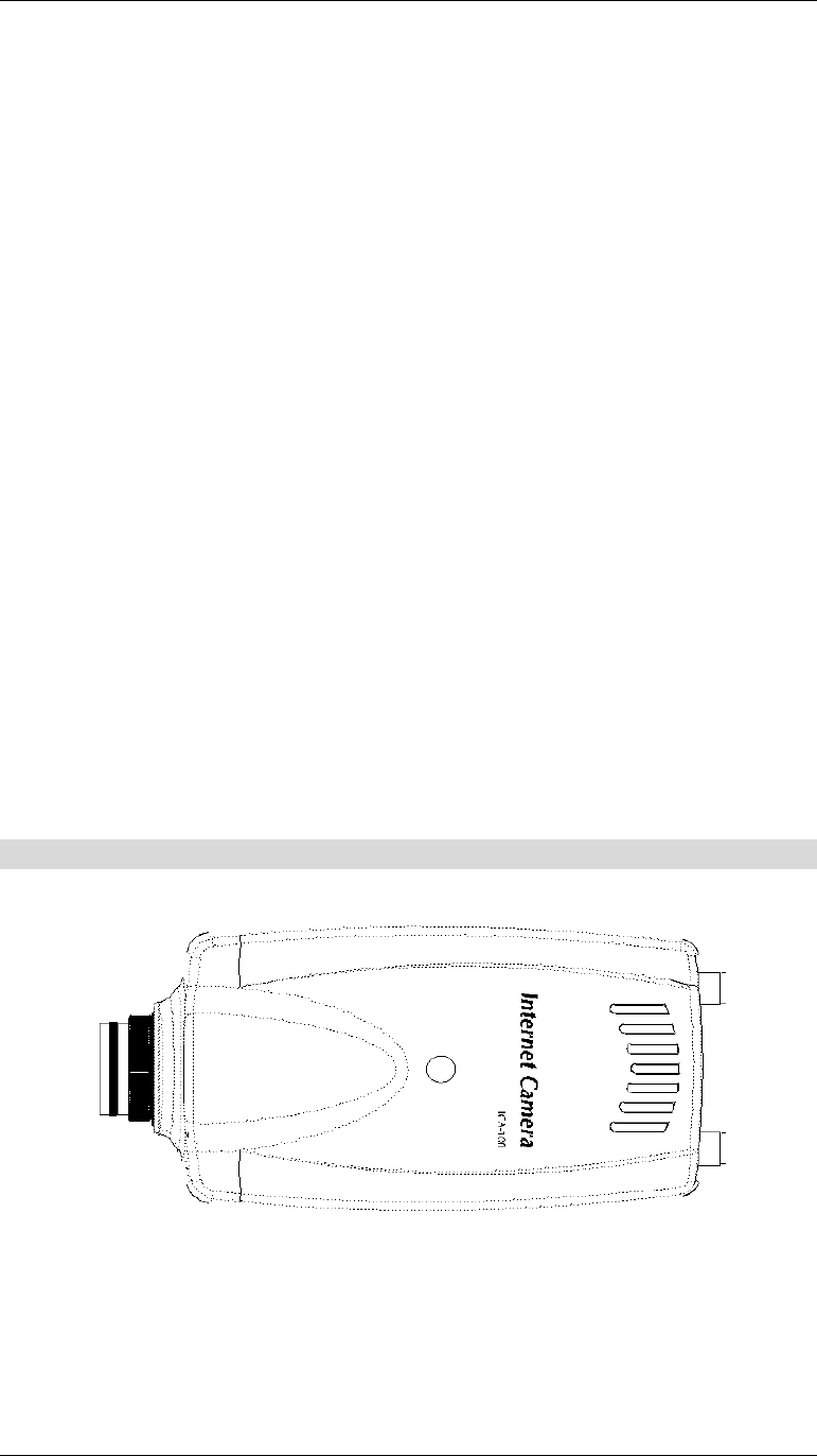
Top Panel
Figure 1-4:Top Panel of ICA-100