


Repair Manual
Macro 5 SLR Camera
35
Section 5. Parts Replacement
Required Tools and Equipment.......................................................................... 37
Electrostatic Discharge Warning ........................................................................ 38
Inspection and Cleaning..................................................................................... 38
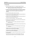
Disassembly/Assembly of Camera..................................................................... 38
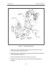
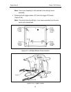
Left/Right Cover (Includes Front Cover)............................................................. 39
1. Removal (Figure 5-1, 5-2 and 5-2a) .......................................................... 39
2. Reassembly............................................................................................... 42
Front Cover ........................................................................................................ 43
1. Removal (Figure 5-3) ................................................................................ 43
2. Reassembly............................................................................................... 44
Rear Cover......................................................................................................... 45
1. Removal (Figures 5-2 and 5-4) ................................................................. 45
2. Reassembly............................................................................................... 46
Bottom Cover ..................................................................................................... 47
1. Removal (Figure 5-5) ................................................................................ 47
2. Reassembly............................................................................................... 48
Strobe PC Board ................................................................................................ 49
1. Removal (Figure 5-6) ................................................................................ 49
2. Reassembly............................................................................................... 50
Trigger PC Boards ............................................................................................. 51
1. Removal (Figure 5-7) ................................................................................ 51
2. Reassembly............................................................................................... 52
S1/S2 PC Board................................................................................................. 53
1. Removal (Figure 5-8) ................................................................................ 53
2. Reassembly............................................................................................... 54
Control Panel ..................................................................................................... 55
1. Removal (Figure 5-9) ................................................................................ 55
2. Reassembly............................................................................................... 56