Repair Manual
Macro 5 SLR Camera
59
Camera Back
Note: Use a dump stick to fully discharge the strobe capacitors before
attempting to remove or replace the camera back.
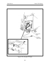
1. Removal (Figure 5-11)
a. Remove the left/right cover assembly as explained on page 39.
b. Remove the rear cover assembly as explained on page 45.
c. Remove the bottom cover as explained on page 47.
d. If applicable, remove the strobe, control, or logic PC boards.
Note: Usually it is not necessary to remove the strobe and logic PC
boards and control panel when removing the camera back - just let
them dangle by their electrical cables. However, if these
components need to be removed during the removal of the camera
back, refer to the applicable disassembly procedures in this section
of the manual.
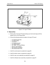
e. Disconnect the following electrical cables from the logic PC board:
• J15 (Piezo)
• J16 (Date Code Module)
• J23 (Film Door Switch)
• J25 (Camera Back Flex)
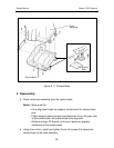
f. Using a torx driver, remove the six (6) screws securing the camera back to
the cone assembly.
g. Lift off the camera back.
Note: Be careful not to loose the plastic support plate (provides the
necessary screw holes that secure the left side of the cone to the
gear side of the camera back).
Caution: Shock Hazard - High Voltage


