


Repair Manual
Macro 5 SLR Camera
58
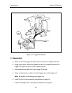
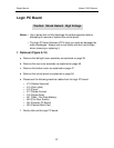
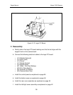
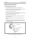
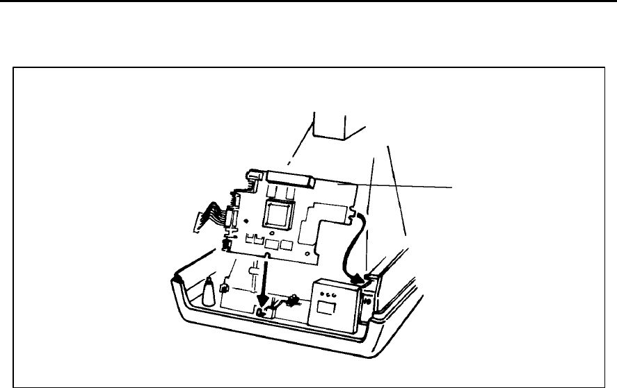
Figure 5-10 Logic PC Board
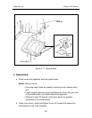
2. Reassembly
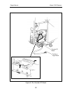
a. Gently slide in the logic PC board making sure that its slot aligns with the
support hook on the camera back..
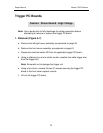
b. Connect the following electrical cables to the logic PC board:
• J13 (Shutter Solenoid)
• J14 (Aim Lights)
• J15 (Piezo)
• J17 (Strobe Control)
• J18 (Strobe Data)
• J21 (VBat - Film Pack Battery)
• J23 (Film Door Switch)
• J24 (Encoder PC Board)
• J25 (Camera Back Flex)
c. Install the control panel as explained on page 56.
d. Install the bottom cover as explained on page 48.
e. Install the rear cover assembly as explained on page 46.
f. Install the left/right cover assembly as explained on page 42.
Logic PC
Board