


Repair Manual
Macro 5 SLR Camera
57
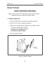
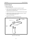
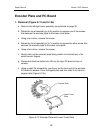
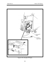
Logic PC Board
Notes: • Use a dump stick to fully discharge the strobe capacitors before
attempting to remove or replace the control panel.
• The logic PC board firmware (CPU chip) can easily be damaged by
static discharges. Always use an anti-static mat and a wrist-strap
when removing or replacing it.
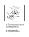
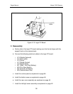
1. Removal (Figure 5-10)
a. Remove the left/right cover assembly as explained on page 39.
b. Remove the rear cover assembly as explained on page 45.
c. Remove the bottom cover as explained on page 47.
d. Remove the control panel as explained on page 55.
e. Disconnect the following electrical cables from the logic PC board:
• J13 (Shutter Solenoid)
• J14 (Aim Lights)
• J15 (Piezo)
• J17 (Strobe Control)
• J18 (Strobe Data)
• J21 (VBat - Film Pack Battery)
• J23 (Film Door Switch)
• J24 (Encoder PC Board)
• J25 (Camera Back Flex)
f. Gently slide out the logic PC board.
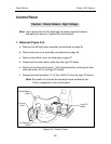
Caution: Shock Hazard - High Voltage