Repair Manual
Macro 5 SLR Camera
49
Strobe PC Board
Note: Use a dump stick to fully discharge the strobe capacitors before
attempting to remove or replace the strobe PC board.
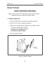
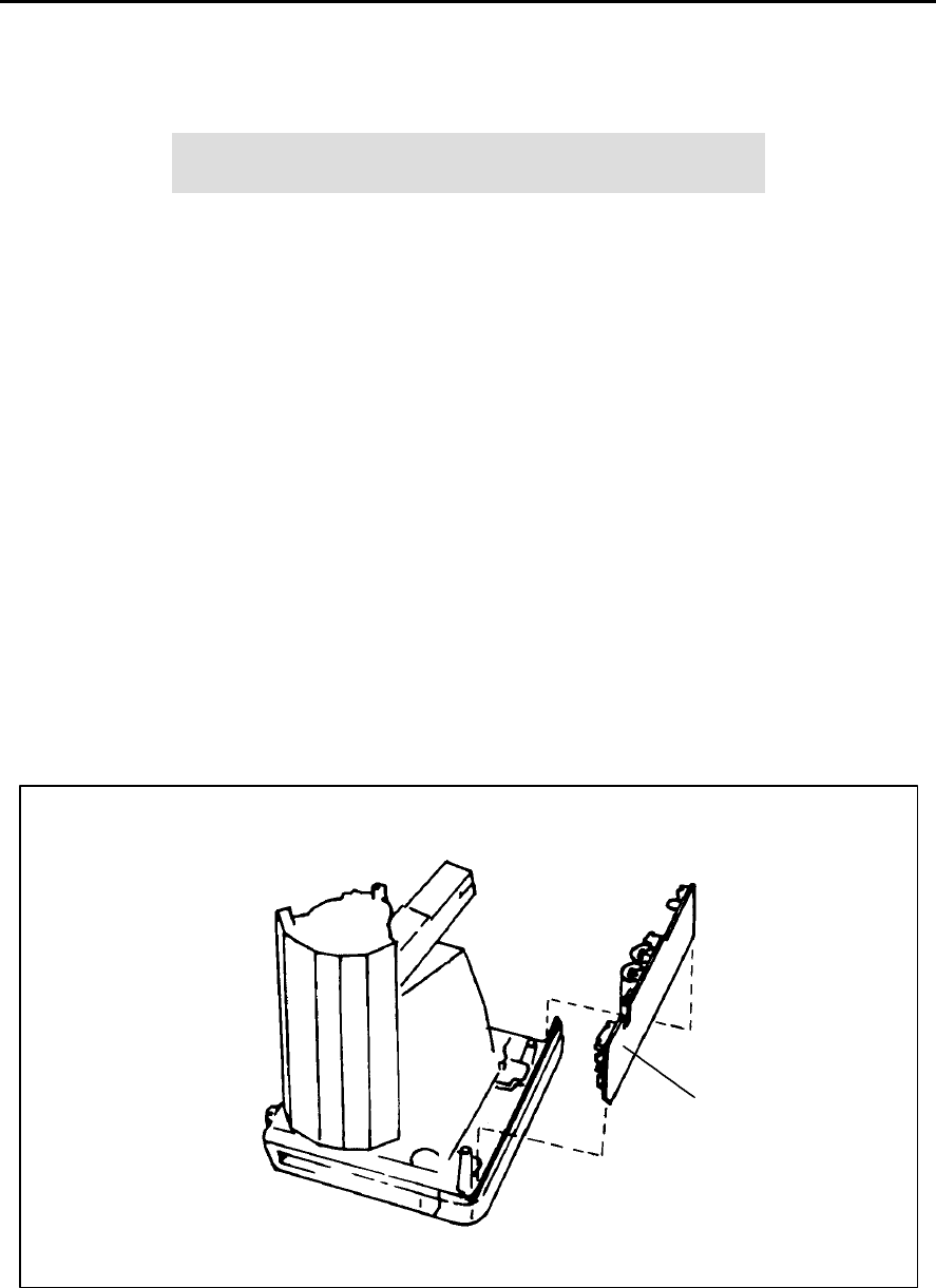
1. Removal (Figure 5-6)
a. Remove the left/right cover assembly as explained on page 39.
b. Remove the rear cover as explained on page 45.
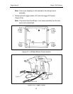
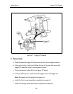
c. Disconnect the following electrical cables from the Strobe PC board:
• J41 (Goes to the left trigger PC board)
• J42 (Goes to the right trigger PC board)
• J43 (Goes to the Logic PC board)
• J44 (Goes to the Logic PC board)
d. Lift out the strobe PC board.
Figure 5-6 Strobe PC Board
Caution: Shock Hazard - High Voltage
Strobe
PC Board


