


Repair Manual
Macro 5 SLR Camera
61
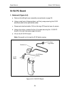
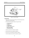
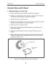
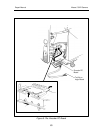
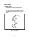
c. Connect the following electrical cables from the logic PC board:
• J15 (Piezo)
• J16 (Date Code Module)
• J23 (Film Door Switch)
• J25 (Camera Back Flex)
Note: If it was necessary to remove the strobe and logic PC boards
and control panel during the removal of the camera back, make
sure that these components are properly reassembled. For
reassembly, refer to the appropriate assembly procedures in this
section of the manual.
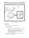
d. Install the bottom cover as explained on page 48.
e. Install the rear cover assembly as explained on page 46.
f. Install the left/right cover assembly as explained on page 42.