


Repair Manual
Macro 5 SLR Camera
56
2. Reassembly
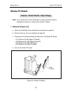
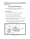
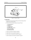
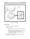
a. Connect electrical cable J11 (X-Sync IN/OUT) to the logic PC board.
Note: Be careful not to break the two black wires soldered to the
X-Sync receptacle on the control panel.
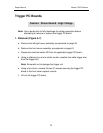
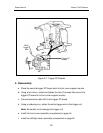
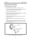
b. Align the two (2) posts on the control panel with the holes on the logic PC
board and then gently push in the control panel. (This connects male
connector J27 on the logic PC board with the control panel).
Note: When pushing the control panel onto male connector J27 on the
logic PC board be careful not to damage (bend or distort) the
connectors pins.
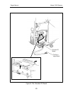
c. Connect the white ribbon cable to the logic PC board.
d. Install the bottom cover as explained on page 48.
e. Install the rear cover assembly as explained on page 46.
f. Install the left/right cover assembly as explained on page 42.