


Overview
Location and Function of Parts
18
Location and Function
of Parts
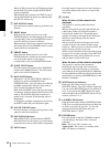
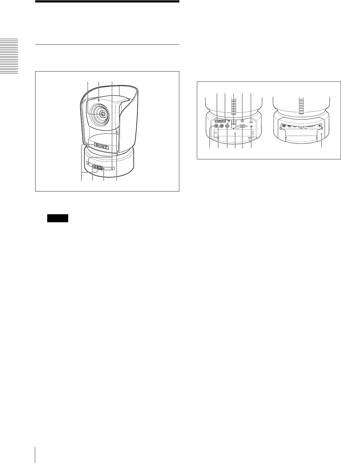
Camera
Front
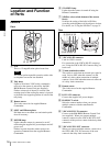
A Lens
This is a 12-magnification optical zoom lens.
Note
You cannot perform pan/tilt operation with a wide
or telephoto conversion lens attached.
B Tally lamp
Lights in red when a VISCA tally command is
received or the camera is selected by the RM-
BR300 Remote Control Unit (not supplied).
Flashes at intervals of about 0.5 seconds if the
rotating speed of the cooling fan motor is lowered
or the motor has stopped regardless of on/off of the
tally lamp.
C Remote sensor
This is the sensor for the supplied Remote
Commander.
D SONY and HD nameplates
Pull them out to turn them over and attach upside
down if necessary.
E POWER lamp
Lights when the camera is connected to an AC
outlet using the supplied AC power adaptor and AC
power cord.
Flashes in green when the camera receives an
operation command from the supplied Remote
Commander.
F STANDBY lamp
Lights when the camera is turned off using the
Remote Commander.
G ND filter select switch (bottom of the camera
block)
Switches the setting of the built-in ND filter
according to the brightness of the subject to be shot.
For details, see “Using the ND Filter” on page 31.
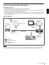
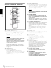
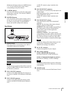
Rear
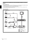
H VISCA RS-422 connector
Used for VISCA control.
For connection to the VISCA RS-422 connector,
see “Using the VISCA RS-422 Connector Plug” on
back cover.
I 75-ohm termination switch
This switch is used when an external sync signal is
used. Set it to OFF when this camera is in the
middle of a daisy chain connection of multiple
cameras. Set it to ON when the camera is at the end
of a daisy chain connection.
J Remote sensor
This is the sensor for the supplied Remote
Commander.
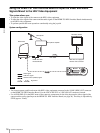
K DC IN 12V connector
Connect the supplied AC power adaptor.
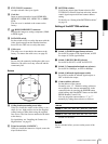
L IR SELECT switch
Select the camera number when you operate
multiple cameras with the same Remote
Commander.
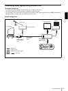
M VISCA RS-232C IN connector
Connect to the RM-BR300 Remote Control Unit
(not supplied). When you connect multiple
cameras, connect it to the VISCA RS-232C OUT
connector of the previous camera in the daisy chain
connection.
N VISCA RS-232C OUT connector
When you connect multiple cameras, connect it to
the VISCA RS-232C IN connector of the next
camera in the daisy chain connection.
1
56 7
32
4
RGB/COMPONENT
VISCA RS-422
1 2 3 4 5 6 7 8 9
EXT SYNC IN
IR SELECT
75
1 2 3
DATA MIX
OFF ON
OFF ON
IN VISCA RS-232C OUT
DC IN 12V
R
q
d
q
f
q
g
q
h
q
j
8 9 0 qa qs
q
k
RGB/COMPONENT
VISCA RS-422
1 2 3 4 5 6 7 8 9
EXT SYNC IN
IR SELECT
75
1 2 3
DATA MIX
OFF ON
OFF ON
IN VISCA RS-232C OUT
DC IN 12V
R
q
l
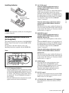
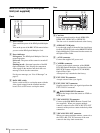
With the cable cover attached