


Installation and Connections
Connections
62
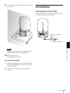
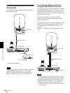
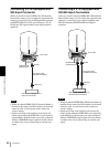
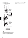
Connecting a VTR Equipped with
SDI Input Connector
When you install an optical HFBK-SD1 SD Interface
Board in the camera, you can output the signal from the
camera by converting it into an SDI signal that conforms
to SMPTE259M (for 59.94i signal format) or ITU-R
BT.656 (for 50i signal format) serial digital interface
standards.
Notes
• When an optional HFBK-SD1 SD Interface Board is
installed in the camera, the DIP switches on the board
cannot be used. Use the menus of the camera for
various settings.
• Signal processing in the interface board causes all
output signals from the HFBK-SD1 to be delayed by
approximately 93H (horizontal sync time) compared
with the YPbPr/RGB output signals from the camera.
A similar delay occurs when using an external sync
signal.
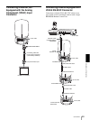
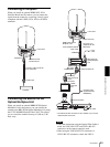
Connecting a VTR Equipped with
HD-SDI Input Connectors
When you install an optional HFBK-HD1 HD Interface
Board in the camera, you can output the signal from the
camera by converting it into a signal compliant with
HD-SDI standards (SMPTE292M serial digital
interface).
Notes
• When an optional HFBK-HD1 HD Interface Board is
installed in the camera, the DIP switches on the board
cannot be used. Use the menus of the camera for
various settings.
• Signal processing in the interface board causes all
output signals from the HFBK-HD1 to be delayed by
approximately 4H (horizontal sync time) compared
with the YPbPr/RGB output signals from the camera.
A similar delay occurs when using an external sync
signal.
SD-SDI
to AC outlet
HFBK-SD1 SD
Interface Board
Connecting cable
with BNC connectors
to SDI input
DVCAM, etc. equipped with an
SDI input comnnector
HD-SDI
to AC outlet
HFBK-HD1 HD
Interface Board
Connecting cable
with BNC connectors
to HD-SDI
input
HDCAM, etc. equipped with an
HD-SDI input comnnectors