


Overview
Location and Function of Parts
24
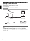
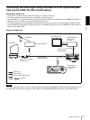
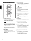
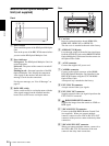
BRU-H700 HD Optical Multiplex
Unit (not supplied)
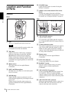
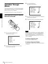
Front
A Power switch
Turns on/off the power of the HD Optical Multiplex
Unit.
Turn on the power of the BRC-H700 camera before
you turn on the HD Optical Multiplex Unit.
B Power indicator
Lit in green: The HD Optical Multiplex Unit is in
normal operation.
Lit in red: The power of the camera is turned off.
Turn it on.
Flashing in red: Abnormal operation of the HD
Optical Multiplex Unit. Display the component
video signal on the monitor and check the error
message. Check also the connection.
For the error message, see “List of Messages” on
page 67.
C DATA MIX switch
Set the switch to ON to overlap the menu with the
video signal output from the installed interface
board. Set it to OFF not to overlap the menu.
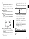
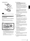
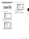
Rear
D Card slot
Insert an optional interface board, HFBK-SD1,
HFBK-HD1, HFBK-XG1 or HFBK-TS1.
The slot cover is attached to the unit at the factory.
E AUDIO OUT L/R jacks
Loop through output of the audio line signal input
from the AUDIO IN jacks on the BRBK-H700 HD
Optical Multiplex Card inserted into the camera via
the Optical Fiber Cable.
F ~AC IN connector
Connect the supplied AC power cord.
G CAMERA connector
Connect to the optical connector of the BRBK-
H700 HD Optical Multiplex Card installed in the
BRC-H700 camera using the CCFC-M100HG
Optical Fiber Cable.
A dustproof cap is attached at the factory.
H EXT SYNC IN connector
Accepts external video sync signals.
I EXT SYNC OUT connector
Supplies external video sync signals input from the
EXT SYNC IN connector.
J RGB/COMPONENT connector
Supplies the images from the camera as YPbPr or
RGB signal.
K VISCA RS-232C IN connector
Connect to the RM-BR300 Remote Control Unit
(not supplied). When you connect multiple
cameras, connect it to the VISCA RS-232C OUT
connector of the previous camera in the daisy chain
connection.
L VISCA RS-232C OUT connector
When you connect multiple cameras, connect it to
the VISCA RS-232C IN connector of the next
camera in the daisy chain connection.
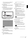
231
IN EXT SYNC OUT
IN
VISCA RS-232C
OUT
CAMERA
~AC IN
VISCA RS-422
AUDIO OUT
L
R
FUNCTION
16
RGB/COMPONENT
7 8
465
9 0 q
d
q
s
q
f
q
a