


Installation and Connections
Connections
64
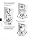
FUNCTION switch on the rear of the Optical
Multiplex Unit (page 25) and the DIP switch on the
bottom of the Remote Control Unit (page 23) are set
to RS-232C or RS-422 correctly.
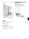
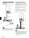
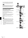
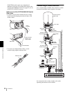
Notes on use of the CCFC-M100HG HD Optical
Fiber Cable
• In order to prevent cable transmission loss, fix the
bend in the cable keeping more than 40 mm (1 5/8
inches) radius.
• To connect two Optical Fiber Cables, use the
extension plug supplied with the cable.
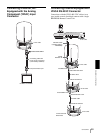
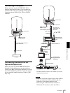
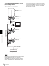
Connecting a Video Switcher
Use a commercially available video switcher to switch
between the multiple camera signals to be output.
For connection with a video switcher, refer to the
Operating Instructions of the switcher.
BRC-H700
CCFC-
M100HG
Keep more than
40 mm (1 5/8
inches) radius.
BRU-H700
CCFC-M100HG
A
B
Extension plug
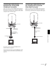
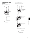
MODE
VISCA
1919
RS-422 ON/OFF
TALLY/CONTACT
RS-232C
CONTACT(TALLY)
!
TAL LY
CONTACT DC IN 12V
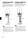
Third to Seventh
BRC-H700
to AC outlet
VISCA RS-
232C IN
RS-232C cable
VISCA RS-232C
OUT
Second BRC-
H700
First BRC-
H700
RM-BR300 Remote
Control Unit
VISCA RS-232C
to
CONTACT
TAL LY/
CONTACT
Connecting cable with D-sub 15-pin connectors (commercially available)
RGB/
COMPONENT
Video switcher (commercially available)
VISCA RS-
232C IN
RS-232C
cable
VISCA RS-232C
OUT
to RGB/
COMPONENT
RS-232C cable
VISCA RS-
232C IN
to component video input
Connecting cable with D-sub 15-pin connectors (commercially available)