


Overview
Location and Function of Parts
25
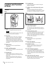
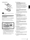
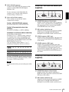
M VISCA RS-422 connector
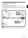
Connect to the VISCA RS-422 connector of the
camera or another BRU-H700 HD Optical
Multiplex Unit.
For the connection to the VISCA RS-422
connector, see “Using the VISCA RS-422
Connector Plug” on back cover.
N VISCA FUNCTION switches
These switches are used for the VISCA
communication settings.
Switch 1 (RS-232C/RS-422 selector)
Set to ON for RS-422, or OFF for RS-232C.
Switch 2 (Communication baud rate
selector)
Set to ON for 38400bps, or OFF for 9600bps.
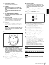
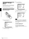
Switches 3 to 5 (Camera address selectors)
Set the address of the camera.
Normally set to “0”. With this setting, addresses
are assigned to the cameras automatically in the
connected order by pressing the POWER button
while holding down the RESET button on the RM-
BR300 Remote Control Unit.
You can assign the camera address “1” to “7”
manually by setting these selectors as follows:
Switch 6 (59.94i/50i signal format selector)
Set to ON for output of 50i signal format, or OFF
for output of 59.94i signal format.
Note
Set the switches before you turn on the power of the
unit.
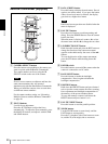
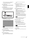
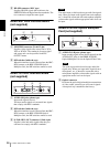
HFBK-SD1 SD Interface Board (not
supplied)
A MONITOR connector (D-sub 9-pin)
Supplies various analog signals such as composite
video, S video, component video and RGB signals.
The output signal can be selected in the DOWN
CONVERTER menu of the camera.
B DIP switches (inside the cap)
When this interface board is inserted into the BRC-
H700 camera or the BRU-H700 HD Optical
Multiplex Unit, the DIP switches cannot be used.
C VIDEO connector (BNC type)
Supplies analog composite signals. The aspect ratio
can be selected in the DOWN CONVERTER menu
of the camera.
D SD-SDI connector (BNC type)
Supplies down-converted SD-SDI signals that
conform to SMPTE259M (for 59.94i signal format)
or ITU-R BT.656 (for 50i signal format) serial
digital interface standards. The aspect ratio can be
selected with the DOWN CONVERTER menu of
the camera.
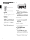
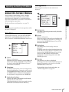
HFBK-HD1 HD Interface Board (not
supplied)
A MONITOR connector (D-sub 15-pin)
Supplies analog video signals (component or
RGB). The output signal can be selected in the HD-
SDI menu of the camera.
B DIP switches (inside the cap)
When this interface board is inserted into the BRC-
H700 camera or the BRU-H700 HD Optical
Multiplex Unit, the DIP switches cannot be used.
Camera
address
01234567
Switch 3 OFF ON OFF ON OFF ON OFF ON
Switch 4 OFF OFF ON ON OFF OFF ON ON
Switch 5 OFF OFF OFF OFF ON ON ON ON
MONITOR
HFBK-SD1
VIDEO SD-SDI
1 2 3 4
MONITOR
HFBK-HD1
HD-SDI HD-SDI
1 2 3