


Installation and Connections
Connections
63
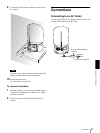
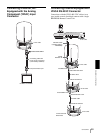
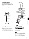
Connecting a Computer
When you install an optional HFBK-XG1 XGA
Interface Board into the camera, you can output the
signal from the camera by converting it into a signal
compliant with the VESA (VGA, XGA or WXGA)
standards.
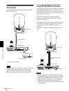
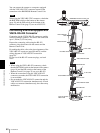
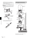
Connecting the BRU-H700 HD
Optical Multiplex Unit
When you install an optional BRBK-H700 Optical
Multiplex Card in the camera, you can connect the
camera to the BRU-H700 Optical Multiplex Unit using
the CCFC-M100HG Optical Fiber Cable. This allows
you to control the camera from up to 1,000 m (3,281
feet) away.
Notes
• When the connection using the Optical Fiber Cable is
made, the VISCA RS-232C and VISCA RS-422
connectors on the camera cannot be used.
• When using the VISCA RS-232C connectors or
VISCA RS-422 connectors, check the VISCA
to AC outlet
MONITOR
HFBK-XG1 XGA
Interface Board
Connecting cable with D-sub
15-pin connectors
to RGB input
Computer
IN EXT SYNC OUT
IN
VISCA RS-232C
OUT
CAMERA
~
AC IN
VISCA RS-422
AUDIO
L
R
FUNCTION
16
RGB/COMPONENT
to AC outlet
BRBK-H700 Optical
Multiplex Card
AC power cord
(supplied with the
BRU-H700
CCFC-M100HG Optical
Fiber Cable
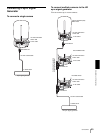
VISCA RS-232C IN
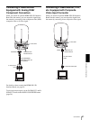
to AC
outlet
CAMERA
BRU-H700 HD
Optical Multiplex
Unit
RGB/
COMPONENT
connecting
cable with D-sub
15-pin
connectors
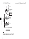
HD monitor, etc.
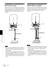
RS-232C cable
(supplied with the
RM-BR300)*
VISCA RS-232C
RM-BR300 Remote Control Unit
to AC outlet
* The VISCA RS-422 connection is also available if you use the
VISCA RS-422 connectors.
Optical connector
to RGB/
component
input