Chapter 4 Viewfinder Screen Indications and Menus 53
Chapter 4 Viewfinder Screen Indications and Menus
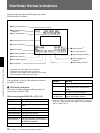
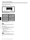
Only when connecting the DSR-1/1P
2 VTR operation status indication
This indicates the VTR’s current operation status
(REC, PLAY, etc.).
3 Time data indication
Time data from the VTR depending on the DISPLAY
switch settings on the VTR are displayed as shown in
the following table.
When using the DSR-1/1P, time data appear during
playback, fast forward, rewind, or recording review.
4 Status display area
One of the following values or messages is displayed
to indicate the camera head’s current status or its
operation status.
• New values when changing camera head’s settings
• Messages indicating progress or results of
adjustments
• The camera head’s current settings (See “Displaying
the Status indications” on page 51.)
5 Camera ID indication
The camera ID is displayed while the camera is in
Color Bar mode.
6 5600K indication
This is displayed when the 5600K button is pressed.
7 Filter setting indication
This shows the setting of the FILTER control.
8 SKIN DTL indication
This appears when the skin detail function is activated.
(See page 64.)
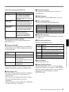
9 White balance indication
The following indications appear.
0 Gain indication
This shows the gain value.
qa Shutter setting indication
When the SHUTTER switch is set to ON, the shutter
speed or CLS frequency set on page 1 <SHUTTER> of
the PAINT menu is displayed here. You can select the
shutter speed or the CLS frequency with the
SHUTTER switch.
Indication Meaning
EZ Operating in EZ mode (The ATW function is
selected.)
ATW The ATW function is selected. (The ATW
button was pressed and the indicator is lit.)
W:A White balance memory A is selected.
W:B White balance memory B is selected.
W:P Preset white balance is selected.
W:M Manual adjustment is performed remotely.
DISPLAY switch
setting
Time data displayed
COUNTER CNT: Tape transport time
TC TCG: a time code data from the time
code generator
TCR: a time code data from the time
code reader
UBG: a user bit data from the user
bit generator
U-BIT
Indication FILTER control setting
CLEAR 1 (CLEAR)
4ND 2 (
1
/4ND)
16ND 3 (
1
/16ND)
64ND 4 (
1
/64ND)
Indication
Meaning
MP TAPE An incorrect type of cassette has
been loaded. (The cassette is
automatically ejected and the
indication disappears in about two
seconds.)
AUDIO 48kHz?
(4 flashes/s)
At back space editing, audio
recording mode has changed from
32 kHz mode (4-channel mode) to
48 kHz mode (2-channel mode).
AUDIO 32kHz?
(4 flashes/s)
At back space editing, audio
recording mode has changed from
48 kHz mode (2-channel mode) to
32 kHz mode (4-channel mode).
ERROR:91-13F
Failure in loading or saving the
cassette memory data.
When other error indication
appears, refer to the operating
instructions for the DSR-1/1P.


