


10
12
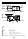
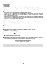
DC IN 12V terminal
Accepts a DC power input (12V).
13
REMOTE terminal
To connect to a RS-232C device for remote control function.
14
SYNC IN/OUT terminal
Used when the camera output signal is synchronized to an external signal or
when a synchronized signal is output. (BNC connector)
15
3G/HD-SDI terminal
Image signal output terminal for 3G/HD-SDI formats. (BNC connector)
16
DVI-D terminal
DVI-D output terminal.
17
KEY LOCK switch
Enables/disables buttons
4
to
11
.
18
FORMAT switch
Switches between 59.94Hz and 50Hz.
19
SYNC switch
14
.
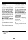
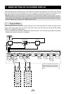
5. CONNECTION
5. 1 Standard Connection
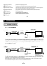
5. 1. 1 DVI Connection
DC power supply
(option)
Lens
(commercial
product)
Camera
Camera
Head
Control unit
Camera Cable
for IK-HD5E
䠄
option
䠅
DVI monitor
DVI-D TV
(commercial product)
DC IN 12V
DVI-D
DVI-D Cable
(commercial
product)
IK-HD5E
IK-HD5H
(option)
*The DVI (digital visual interface) is the connection interface standard for fl at-panel display (FPD) such as LCD
displays. There are three types of DVI connectors, namely DVI-I (for both digital/analog), DVI-D (exclusively for digital)
and DVI-A (exclusively for analog). Use a commercially available DVI-D cable for this camera control unit.
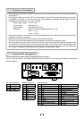
5. 1. 2 SDI Connection
DC power supply
(option)
Lens
(commercial
product)
Camera
Camera
Head
Control unit
Camera Cable
for IK-HD5E
(option)
SDI monitor
3G/HD-SDI TV
(commercial product)
DC IN 12V
3G/HD-SDI
Coaxial cable, 75Ω
(commercial
product)
IK-HD5E
IK-HD5H
(option)
*The SDI (serial digital interface) is a high-speed serial interface standard used mainly commercial video
equipment. This unit supports both HD-SDI and 3G-SDI.
When image output is 1080p, 3G-SDI output is used. When image output is 1080i, HD-SDI output is used.
Use a 3G/HD-SDI compatible cable to connect to the 3G/HD-SDI terminal.