


9
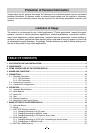
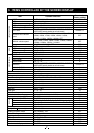
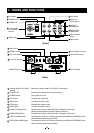
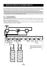
4. NAMES AND FUNCTIONS
12345
8796
2
10
18
1
9
17
3
11
19
4
12
20
5
13
21
6
14
22
7
15
23
8
16
24
3
4
2
1
ON
OFF
50
59.94
IN
OUT
FORMAT SYNCKEY LOCKDC IN 12V
REMOTE
3G/HD-SDI
SYNC IN/OUT
DVI-D
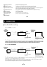
Camera cable
for “IK-HD5H”
terminal
POWER switch
POWER LED
FILE button
GAIN button
DISP button
PAGE button
MENU UP
(SHD) button
MENU DOWN
button
DATA UP
(AWB) button
DATA DOWN
(ABB) button
[Front]
[Rear]
SYNC switch
REMOTE terminal
KEY LOCK switch
3G/HD-SDI terminal
DVI-D terminal
DC IN 12V terminal
FORMAT switch
SYNC IN/OUT terminal
1
Camera cable for “IK-HD5H”
terminal
Where the camera cable for “IK-HD5H” is connected.
2
POWER LED
Illuminates to indicate the unit is powered on.
3
POWER switch
Turns power on or off.
4
FILE button
To switch the scene fi les.
5
GAIN button
To change the gain mode.
6
DISP button
Changes the display mode.
7
PAGE button
To switch and select menus.
8
MENU UP (SHD) button
To select the function to be confi rmed or changed on the menu.
(Also used when performing auto shading correction.)
9
MENU DOWN button
To select the function to be confi rmed or changed on the menu.
10
DATA UP (AWB) button
To change the value of the function selected by the MENU (UP/DOWN) button.
(Also used when performing an AWB.)
11
DATA DOWN (ABB) button
To change the value of the function selected by the MENU (UP/DOWN) button.
(Also used when performing an ABB.)