


AXIS 211M - I/O Terminal Connector
34
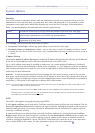
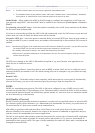
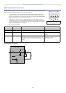
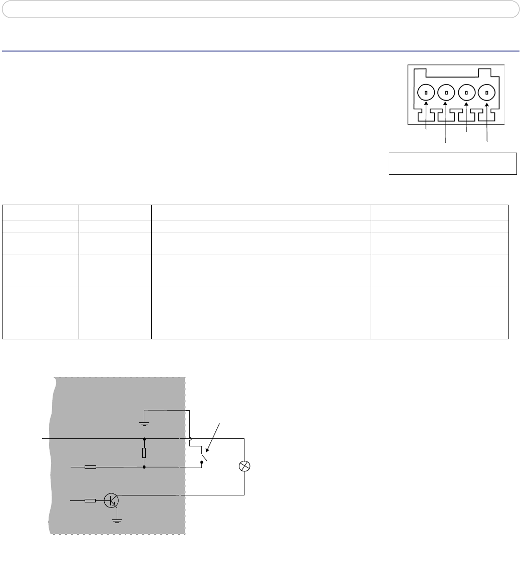
I/O Terminal Connector
The I/O terminal connector is used in applications such as motion detection, event triggering,
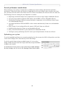
Pin 3
Pin 4
Pin 2
Pin 1
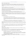
Terminal connector. Note that the pins
are numbered 1-4, right to left.
time
lapse recording and alarm notifications. It provides the interface to:
• 1 transistor output - For connecting external devices such as relays and LEDs. Con-
nected devices can be activated by AXIS VAPIX AP, output buttons on the Live View
page or by an Event Type. The output will show as active (shown under Event Config
-
uration > Port Status) if the alarm device is activated.
• 1 digital input - An alarm input for connecting devices that can toggle between an
open and closed circuit, for example: PIRs, door/window contacts, glass break detectors,
etc. When a signal is received the state changes and the input becomes active (shown
under Event Configuration > Port Status).
• Auxiliary power and GND
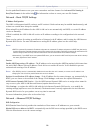
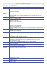
GND 1
5V DC Power 2 Can be used as an alternative power supply (7-20VDC) or to power
auxiliary equipment +5VDC (100mA).
Max load = 100mA
Digital Input 3 Connect to GND to activate, or leave floating (or unconnected) to
deactivate.
Must not be exposed to voltages greater
than
20VDC
Transistor Output 4 Uses an open-collector NPN transistor with the emitter connected
to the GND pin. If used with an external relay, a diode must be
connected in parallel with the load, for protection against voltage
transients.
Max load =100mA
Max voltage = 24VDC
(to the transistor)
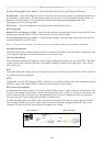
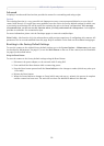
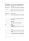
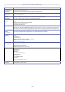
Connection diagram
o
z
AXIS 211M
5V
max. 100mA
e.g. pushbutton
4
o
3
o
o
2
1
Function Pin number Notes Specifications