


2-3
Cisco Video Surveillance 2630 IP Dome User Guide
OL-24130-02
Chapter 2 Getting Started
Installing the Cisco Video Surveillance 2630 IP Dome
• Run a power cable from a 24 VAC power adapter to the mounting location.
Use a cable gauge that is appropriate for the distance from the IP dome to the power supply (consult
a qualified electrician for more information). The terminal connectors on the IP dome support
gauges from 14 AWG to 24 AWG. At the end of the wire that attaches to the IP dome, strip enough
cable housing to allow each wire to be stripped to 1/4 inch (6.25 mm).
Note To achieve IP66 rated protection for the IP dome when mounting outdoors, you must use the
conduit base (CIVS-IPCA-1006=) or Pendant Cap (CIVS-IPCA-1010=) mounting
accessory.
• If you will connect an external speaker, microphone, or both to the IP dome, run audio cable from
each device to the mounting location.
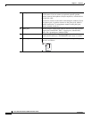
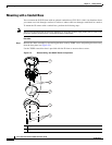
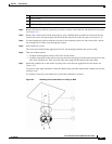
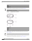
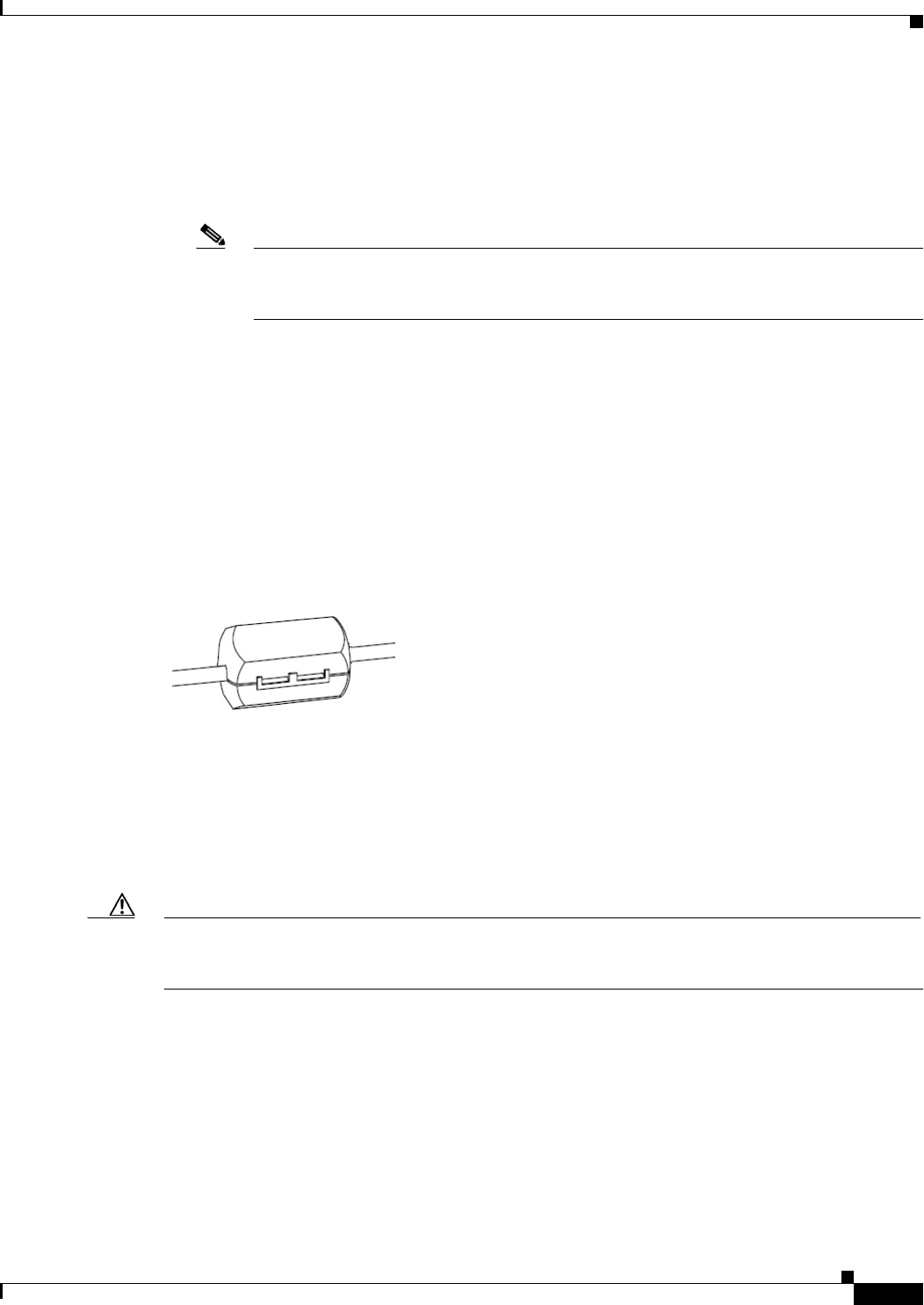
To attach the audio cable to the IP dome, you will need the white snap on ferrite core and audio
Y
cable that are included in the optional audio/video cables accessory kit, which you can purchase
from Cisco (Cisco part number CIVS-IPCA-1017=). Attach the white snap on ferrite core to the
audio Y
cable (from the optional accessory kit) at approximately 10 inches (25 cm) away from
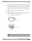
where the cable connects to the IP dome. To do so, lift the tabs to open the ferrite core, pass the cable
through the ferrite core (do not loop the cable), then snap the ferrite core shut to secure it on the
cable. See
Figure 2-1.
Figure 2-1 Passing the Audio Cable through a Ferrite Core
• If you will use external input devices or output device that trigger alarms (connect through alarm
input ports) or respond to alarms (connect through alarm output ports), run cables from each device
to the mounting location. You can use up to two input devices and up to two output devices.
• If the dome requires a waterproof installation, use waterproof tubing to protect the cables that you
run to the dome.
• Have an analog monitor available on which to view video while adjusting the field of view.
Caution Use the analog monitor only to point the IP camera to the desired field of view; do not use it to manually
adjust the focus or zoom. Doing so may damage the lens. Instead, use the Focus/Zoom window in the
configuration software to remotely set the focus and zoom for the IP camera.
• Have the following tools available:
–
Phillips-head screwdriver
–
Small flat-head screwdriver
–
Cutting tool to cut a hole in a ceiling tile (required for mounting in a ceiling tile)
–
Drill bits (required for surface mounting on a solid surface)