


Page 6
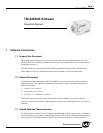
TM-4200GE Software
Connectors
2 Connectors
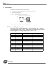
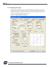
The camera has two sockets, as shown in Figure 6 below:
• 12-pin Hirose for power, trigger, RS-232 communication and TTL I/O.
• RJ-45 for Gigabit Ethernet.
FIGURE 6. TM-4200GE Back Panel Connectors
These connectors are described in Section 2.1 and Section 2.2.
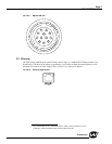
2.1 Power and Signals Connector
The GE camera receives power and signal through a 12-pin Hirose connector. Table 1 lists the pin
layout and describes the function of each pin. The table lists the GPIO assignments for the relevant pins.
A magnified illustration of each pin’s assignment follows in Figure 7 on page 7.
TABLE 1. Hirose Connector, Pin Assignment
Pin # Definition Description GPIO Assignment
1 GND Power ground
2 +12V DC Power supply in
3 GND Analog ground (video)
4 Analog Video For auto iris lens drive O
5 GND Ground
6Vinit Vinit I
7 External VD I: Standard O: Option I/O
8 STROBE Strobe output O
9 External HD I: Standard O: Option I/O
10 Reserved Reserved
11 Reserved Reserved
12 Reserved Reserved
GigE
POWER