Page 49
TM-4200GE Hardware
Installation
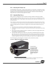
8.2.2 (b) Ethernet Connector
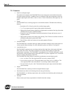
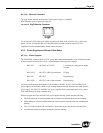
The GigE socket, marked on the camera’s back panel as GigE, is a standard
RJ-45 Ethernet socket as shown in Figure 50.
FIGURE 50. GigE Ethernet Connector
Use at least cat5e UTP cables (cat6 cables are preferred). Refer to the Cam2Net User’s Manual for
details. JAI Inc. recommends the use of shielded cables to reduce emissions and for CE/FCC
compliance. Double-shielded cables further reduce emissions.
8.2.3 Power Supplies and Power Cable Setup
8.2.3 (a) Power Supplies
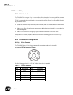
The TM-4200GE camera requires 12V DC power that is obtained through the 12-pin connector located
on the rear panel of the camera. JAI Inc. recommends the following power supplies:
PD-12UU 100-240V AC/12V DC 1.2A universal voltage power supply,
US Plug
PD-12UUP PD-12UU with12-pin connector US plug
PD-12UE PD-12UU European plug
PD-12UEP PD-12UU with 12-pin connector European plug
For users providing power through the 12-pin connector, the PD-12P, PD-12UEP and PD-12UUP
power supplies are available with the 12-pin mating connector already attached to the leads from the
power supply. The PD-12UU and PD-12UE power supplies can be connected to the JAI Inc. power
cable either directly or using a terminal strip.
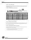
When wiring the PD-12UU and PD-12UE power supplies directly, please note the following:
• The lead ends must be twisted together and tin-soldered for strength and electrical continuity.
• Shrink tubing or a similar insulator should be used to prevent exposed leads from touching and
shorting.
• The +12V lead is marked with a red stripe or white lettering; be sure not to reverse the leads.
• All connections must be properly insulated to prevent shorting.
GigE


