


Page 30
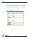
TM-4200GE Software
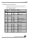
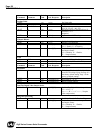
GigE Series Camera Serial Commands
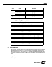
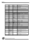
Bit 2 Shutter 2
0000=Async no shutter 0001 - 1000=Async
preset shutters 1-8
Bit 3 Shutter 3
1001=PWC 1010=PIV Fixed Exposure
1011=PIV PWC
Bit 4 Shutter Mode 0
00=Continuous Preset Shutter 01=Trigger
Preset Shutter
Bit 5 Shutter Mode 1
10=Trigger Programmable Shutter
11=Continuous Programmable Shutter
Bit 6 Data Depth 0 00=8bit 01=10bit
Bit 7 Data Depth 1 10=12bit
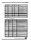
Byte 11
Function Flag
2
Bit 0 Look-up table 0 00=Linear 01=Gamma.45
Bit 1 Look-up table 1 10=User Knee Table
Bit 2 Rsvd
Bit 3
Camera Control
Signals
0=CameraLink Connector 1=Hirose 12pin
Connector
Bit 4 Rsvd
Bit 5
Trigger Signal
Polarity 0=Active Low 1=Active High
Bit 6
Dual / Signal
Tap 0=Dual Tap 1=Single Tap
Bit 7
Positive /
Negative LUT 0=Positive LUT 1=Negative LUT
Byte 12
Function Flag
3
Bit 0
R Channel Auto
Fine Gain 0=Disable 1=Enable
Bit 1
R Channel Auto
Fine Offset 0=Disable 1=Enable
Bit 2 Rsvd
Bit 3 Rsvd
Command Parameter End of Cmd Description
Bit 4
Blemish
Compensation 0=Disable 1=Enable
Bit 5 Rsvd
Bit 6 Password 0=Disable 1=Enable
Bit 7 Test Pattern 0=Disable 1=Enable
Byte 13, 14 (X1, Y1) Coordinate for Knee 1 (X1, Y1=H'00 - H'FF)
Byte 15, 16 (X2, Y2) Coordinate for Knee 2 (X2, Y2=H'00 - H'FF)
Byte 17, 18
Start Line of
Programmable
Scan Area
Start Line of Programmable Scan Area
(H'0000 - H'07FF)
Byte 19, 20
Total Lines of
Programmable
Scan Area
Total Lines of Programmable Scan Area
(H'0001 - H'0800)
Byte 21, 22
Shutter Speed
of
Programmable
Shutter
Shutter Speed of Programmable Shutter
(H'0000 - H'081F)
Byte 23, 24 Vsub Voltage Vsub Voltage (H'0600 - H'0D00=7.8V - 17V)