


16
Control reference guide (continued)
AC IN
SIGNAL
GND
AES/EBU
CH1•2
IN
CH3•4
IN
CH1•2
OUT
CH3•4
OUT
SDI
IN OUT
1
2
3
(SUPER)
ACTIVE
THROUGH
ANALOG ANALOGREMOTO
Y
VIDEO
IN
P
B
P
R
Y
P
B
P
R
ON
OFF
75Ω
REF VIDEO
IN
ON
OFF
75Ω
1
2
3
(SUPER)
REMOTO IN
ENCODER REMOTE
RS-232C
CH1
CH3
CH1
CH3
CH2
AUDIO
IN
CH4
CH2
CH4
AUDIO
OUT
DVCPRO/
DV
(OPTION)
100BASE-TX
TC
IN
TC
OUT
MON
L
MON
R
SERVICE ONLY
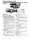
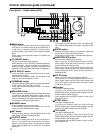
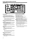
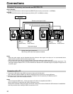
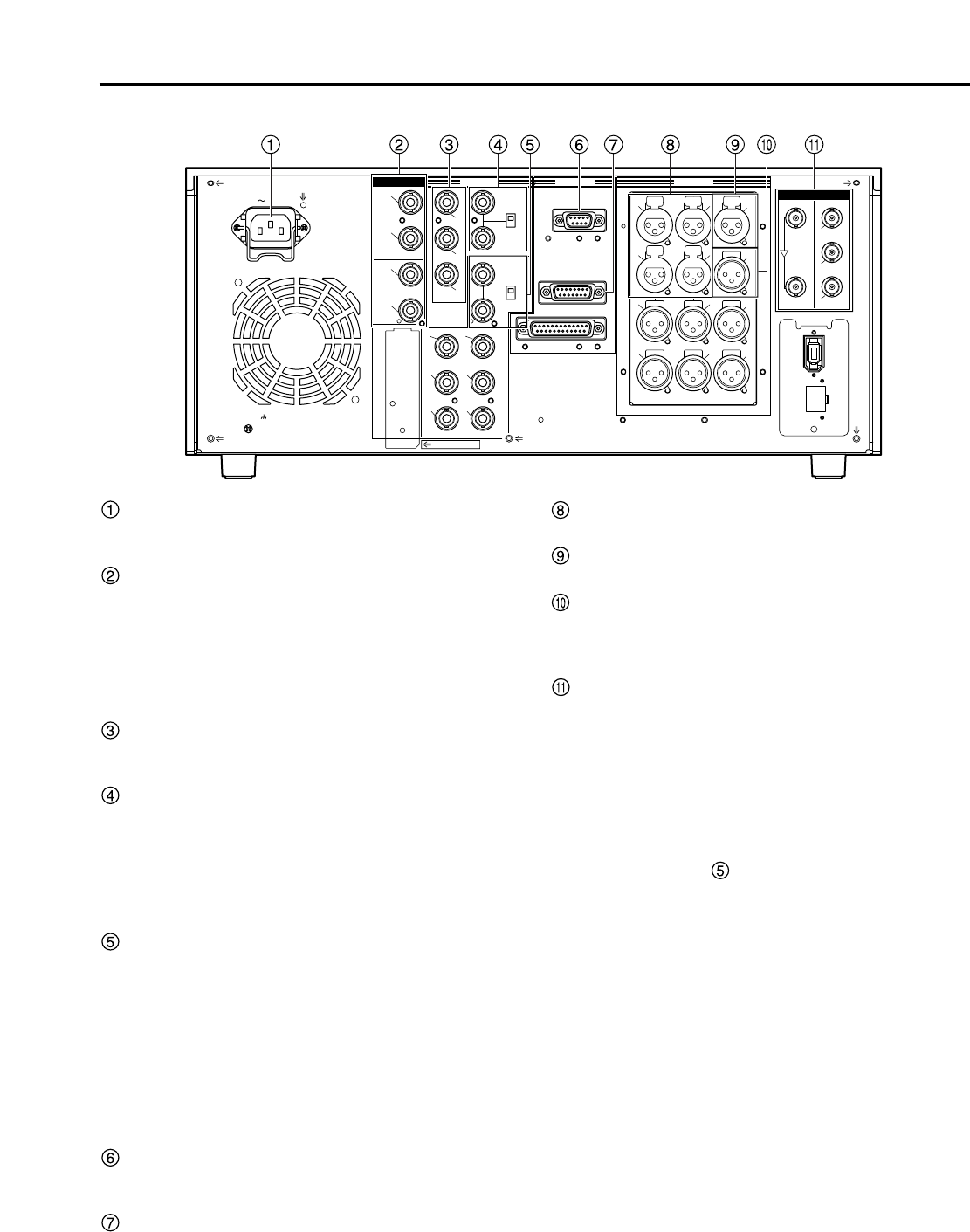
Rear Panel (1/2)
AC IN socket
Connect one end of the power cord supplied to this
socket and the other end to the power outlet.
DIGITAL AUDIO IN and OUT connectors
These are the input and output connectors for digital
audio signals that comply with the AES/EBU standards.
ANALOG COMPONENT VIDEO IN connectors
The analog component video signals are input to these
connectors.
ANALOG COMPOSITE VIDEO IN connectors
and 75 Ω termination switch
Input connectors for analog composite video signals.
A loop-through configuration is featured for each pair of
input connectors.
For termination at the memory card recorder, set the
switch to [ON].
REF VIDEO IN connectors and 75 Ω termination
switch
Input connectors for reference video signals.
Input a reference signal with color burst.
For termination at the memory card recorder, set the
switch to [ON].
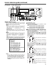
Remote control connectors
Connect the memory card recorder to an external
controller.
ENCODER REMOTE connector
Connect the memory card recorder to an external
encoder to adjust video output signal settings from an
external component.
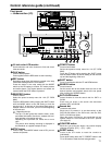
Note:
Video and audio output may be disturbed when the
reference video signal is not input, so use a system
which inputs the reference video signal.
Note:
The digital audio signals must be synchronized with
the video input signals; otherwise noise will be
generated in the audio output signals.
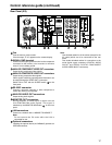
ANALOG AUDIO IN connectors
These are the analog audio input connectors.
TIME CODE IN connector
Use to record an external time code onto the cards.
TIME CODE OUT connector
Outputs the playback time code during playback.
Outputs the time code generated by the internal time
code generator during recording.
SERIAL DIGITAL COMPONENT AUDIO and
VIDEO IN and OUT connectors (optional)
Installing an SDI interface board (optional board AJ-
YA755G) in the memory card recorder enables
input/output of digital component audio/video signals
conforming to the SMPTE259M-C standard.
Video signals containing superimposed information can
be output through the SDI OUT 3 connector.
To turn the superimposed information ON or OFF, use
the SUPER switch on the front panel.
Note:
The digital audio signals must be synchronized with
the video input signals; otherwise noise will be
generated in the audio output signals.