


17
Control reference guide (continued)
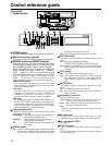
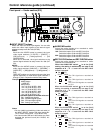
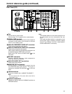
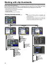
Fan
Cool the memory card recorder.
If the fan stops, “E-10” appears on the counter display.
SIGNAL GND terminal
Connect to the signal ground terminal on the component
connected to the memory card recorder to minimize
noise. It is not a safety ground.
ANALOG COMPONENT VIDEO OUT connectors
Output analog component video signals.
ANALOG COMPOSITE VIDEO OUT connectors
Output analog composite video signals.
Video signals containing superimposed information can
be output through the VIDEO OUT 3 connector.
Switch ON or OFF with the SUPER switch on the
front panel.
RS-232C connector
Connect a personal computer or other component to
control the memory card recorder.
ANALOG AUDIO OUT connectors
Output analog audio signals.
MONITOR OUT connectors
During playback, a mixed signal is output from the
CH1/CH2/CH3/CH4 audio signals. This signal is
switched by the MONITOR MIX button on the front
panel.
LAN connectors
Connect to a network with a 100BASE-TX/10BASE-T.
Note:
Do not remove the P2 cards while the LAN is
connected for use.
Optional connectors
Installing the optional board (AJ-YAD850G) provides an
IEEE1394 interface.
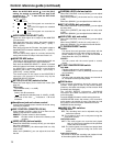
DVCPRO/
DV
(OPTION)
100BASE-TX
AC IN
SIGNAL
GND
AES/EBU
CH1•2
IN
CH3•4
IN
CH1•2
OUT
CH3•4
OUT
SDI
IN OUT
1
2
3
(SUPER)
ACTIVE
THROUGH
ANALOG ANALOGREMOTO
Y
VIDEO
IN
P
B
P
R
Y
P
B
P
R
ON
OFF
75Ω
REF VIDEO
IN
ON
OFF
75Ω
1
2
3
(SUPER)
REMOTO IN
ENCODER REMOTE
RS-232C
CH1
CH3
CH1
CH3
CH2
AUDIO
IN
CH4
CH2
CH4
AUDIO
OUT
TC
IN
TC
OUT
MON
L
MON
R
SERVICE ONLY
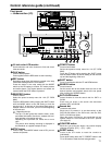
Rear Panel (2/2)
Note:
Use shielded cables for all the cables (except for the
AC cable) which are to be connected to the rear
panel.
Use double-shielded cables for connection to the
serial digital signal connectors (DIGITAL AUDIO
IN/OUT and SERIAL DIGITAL COMPONENT
AUDIO VIDEO IN/OUT connectors).