


20
Connections
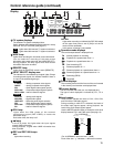
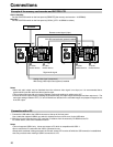
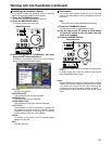
Example of the memory card recorder and DVCPRO VTR
Source machine:
Set the CONTROL switch on the front panel to [REMOTE] (the memory card recorder : AJ-SPD850).
Recorder:
Set the CONTROL switch on the front panel to [LOCAL] (VTR : AJ-SD955 or others).
Notes:
•Video and audio output may be disturbed when the reference video signal is not input, so it is recommended that a
system which inputs the reference video signal be used.
•This unit does not come with color framing settings. Perform the settings for editing using “2F.”
•In terms of the EE output images (including the V BLANK data), the input images are delayed and then output as is. The
menu item settings related to VITC, CC and V BLANK are reflected in the recorded images and playback images but not
in the EE output.
AC IN
SIGNAL
GND
AES/EBU
CH1•2
IN
CH3•4
IN
CH1•2
OUT
CH3•4
OUT
SDI
IN OUT
1
2
3
(SUPER)
ACTIVE
THROUGH
ANALOG ANALOGREMOTO
Y
VIDEO
IN
P
B
P
R
Y
P
B
P
R
ON
OFF
75Ω
REF VIDEO
IN
ON
OFF
75Ω
1
2
3
(SUPER)
REMOTO IN
ENCODER REMOTE
RS-232C
CH1
CH3
CH1
CH3
CH2
AUDIO
IN
CH4
CH2
CH4
AUDIO
OUT
TC
IN
TC
OUT
MON
L
MON
R
SERVICE ONLY
AC IN
SIGNAL
GND
AES/EBU
CH1•2
IN
CH3•4
IN
CH1•2
OUT
CH3•4
OUT
SDI
IN OUT
1
2
3
(SUPER)
ACTIVE
THROUGH
IN OUT
OPUTION
1
2
ANALOG ANALOGREMOTO
Y
VIDEO
IN
P
B
P
R
Y
P
B
P
R
ON
OFF
75Ω
REF VIDEO
IN
ON
OFF
75Ω
1
2
3
(SUPER)
REMOTO IN
REMOTO OUT
ENCODER REMOTE
RS-232C
CH1
CH3
CH1
CH3
CH2
AUDIO
IN
CH4
CH2
CH4
AUDIO
OUT
TC
IN
TC
OUT
MON
L
MON
R
SERVICE ONLY
DVCPRO/
DV
(OPTION)
100BASE-TX
Source machine Recorder
Remote control signal (9 pin)
OFF
With SDI interface board (optional) installed
ON
Digital audio signal
Analog video signal (component)
With analog video input board (optional) installed
To video
monitor device
To audio
monitor device
To video
monitor device
To audio
monitor device
Reference signal
generator
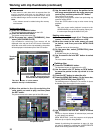
Connection with a PC
1. Connect the USB cable to the USB2.0 connector at the top of the front panel.
Use a cable that supports USB2.0 (one which is shielded and has a ferrite core) for the USB cable.
2. With the unit now connected to the PC, install the P2 software from the accessory CD-ROM into the PC.
For further details, refer to the installation manual.
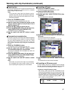
Notes:
•This unit supports USB2.0 only. It does not support a PC which is compatible with USB1.1.
•Do not remove the P2 cards while the USB is connected for use.
•Except while card data is being accessed, the P2 card access LED remains off while the USB connection is established.
•Use only one deck when making a USB2.0 connection to a PC.