


74
The underlining indicates the factory settings.
Any changes to the settings can be made using the
setup menu items listed below.
RS-232C interface
The memory card recorder can be operated by commands
when the RS-232C interface is used.
(See command table on pages 75, 76)
Conditions for acknowledging commands
from RS-232C interface
•The front panel REMOTE button is lit
•The setup menu No. 204 (RS232C SEL) must be ON.
If the above conditions are not met, [ACK] + [STX] ER001
[EXT] is returned to the external deck.
Whether the [ACK] code is returned depends on the
setting which has been selected for setup menu item No.
209 (RETURN ACK).
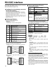
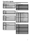
Hardware specifications
External interface specifications
•Connector specifications
Connector:
D-SUB 25-pin (crossover cable supported)
Pin No.
1
2
3
4
5
6
7
20
Signal
FG
RXD
TXD
CTS
RTS
DTR
SG
DSR
Description
Protective ground
(Frame ground)
Received data
(Data is sent to PC.)
Transmitted data
(Data is received from PC.)
Clear to send
(Shorted with pin 5.)
Request to send
(Shorted with pin 4.)
Data terminal ready
(No processing)
Signal ground
(Signal ground)
Data set ready
(+ voltage output after communication
enable status)
•Example of connection with controller (PC)
(Using crossover cable with D-SUB 25-pin connectors)
1
2
3
4
5
6
7
20
FG
TXD
RXD
RTS
CTS
DSR
SG
DTR
1
2
3
4
5
6
7
20
FG
RXD
TXD
CTS
RTS
DTR
SG
DSR
deck side
PC side
(D-SUB 25-pin connector)
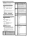
(Using crossover cable with D-SUB 9-pin and 25-pin
connectors)
2
3
4
5
6
7
8
RXD
TXD
DTR
SG
DSR
RTS
CTS
1
2
3
4
5
6
7
20
FG
RXD
TXD
CTS
RTS
DTR
SG
DSR
deck side
PC side
(D-SUB 9-pin connector)
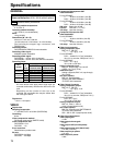
Software specifications (Protocol)
Communication parameters
Communication
system
Communication
speed
Bit length
Stop bit
Parity bit
ACK code
Asynchronous, full duplex
300/600/1200/2400/4800/9600
7bit/8 bit
1 bit/2 bit
NONE
/ODD/EVEN
ACK code returned
/ACK code not
returned
Note:
The ACK code is what is returned from
the memory card recorder to the
controller when data has been
successfully sent from the controller.
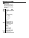
Send format
[controller (PC)
→ memory card recorder]
Data format
20H<XX<7FH
(XX = ASCII code: symbols, numbers upper-case
letters)
[command] :
Command identifier; a 3-byte identifier (ASCII code:
symbols, numbers, upper-case letters) is sent as the
command.
[:] :
This code serves as a delimiter between the
command and data.
[data] :
Data (ASCII code: symbols, numbers, uppercase
letters) can be added in the number of bytes
required.
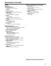
Outline of send procedure from controller
•The send command starts with STX (start of text = 02h).
The command is then identified by COMMAND which
follows and the data is added as required.
The format ends with ETX (end of text = 03h).
•When a different command is to be sent, a response is
awaited from the memory card recorder, and then the
command is sent.
•If STX is sent again before ETX is sent, the receive data
buffer inside the memory card recorder is cleared. A
command error is returned to the controller, and the
data is newly processed with STX which was received
again at the head.
[STX] [command] [:] [data] [ETX]
02h XX XX XX 3Ah XX.....XX 03h
Communication
parameter
Communication
speed
Bit length
Stop bit
Parity bit
ACK code
Setup menu item
No.205 BAUD RATE
No.206 DATA LENGTH
No.207 STOP BIT
No.208 PARITY
No.209 RETURN ACK