


20
Connections
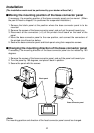
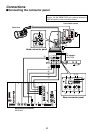
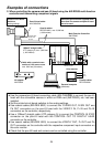
$Connecting the base connector panel
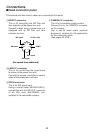
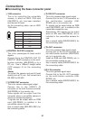
51394 connector
This is for controlling the convertible
camera, in which an IEEE 1394 card
(AW-PB310), etc. has been installed,
and the pan-tilt head.
As the connecting cable, use an IEEE
1394 cable.
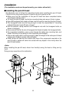
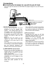
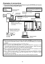
6CONTROL IN IP/RP connector
This is for camera/pan-tilt head control
signals.
Connect this to the CONTROL OUT TO
PAN/TILT HEAD connector on the multi-
function controller (AW-RP605) or to a
PC, etc. Use a 10BaseT straight cable
(UTP category 5) for the connecting
cable.
<Note>
To control the camera and pan-tilt head
directly from a PC, etc., first convert from
RS-232C to RS-422.
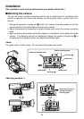
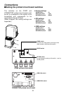
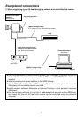
7Y/VIDEO OUT connector
This is for camera video signal output.
Connect this to the VIDEO/Y IN
connector on the multi-function controller
(AW-RP605) or to a monitor, etc.
Video signals will be output from this
connector when a convertible camera is
used as a standard accessory.
Y signals can be output when an RGB
card (AW-PB302) is installed in the
convertible camera for use.
Use a coaxial cable (BELDEN 8281) for
the connecting cable.
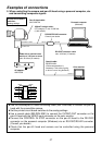
8Pr/SDI OUT connector
This is for camera video signal output.
Connect this to the Pr IN connector on
the multi-function controller (AW-
RP605), etc. or to a monitor, etc.
Pr signals can be output when an RGB
card (AW-PB302), etc. is installed in the
convertible camera for use.
Alternatively, SDI signals can be output
when an SDI card (AW-PB304), etc. is
installed in the convertible camera for
use.
Use a coaxial cable (BELDEN 8281) for
the connecting cable.
9Pb OUT connector
This is for camera video signal output.
Connect this to the Pb IN connector on
the multi-function controller (AW-RP605,
etc.) or to a monitor, etc.
Install an RGB card (AW-PB302), etc. in
the convertible camera for use.
Use a coaxial cable (BELDEN 8281) for
the connecting cable.
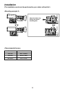
:G/L IN connector
This is for genlock signal input.
Connect this to the G/L OUT connector
on the multi-function controller (AW-
RP605), etc.
Use a coaxial cable (BELDEN 8281) for
the connecting cable.
Pin No. Signal
1 DC 12V
2 GND
3
TPB 2
4 TPB
5
TPA 2
6 TPA
12
34
56