


24
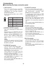
O I
REMOTE
VIDEO/Y IN
Pr IN
Pb IN
G/L OUT
Y IN
Pr IN
Pb IN
VIDEO/Y OUT
Pr OUT
Pb OUT
CONTROL IN IP/RP
Y/VIDEO OUT
Pr/SDI OUT
Pb OUT
G/L IN
CONTROL OUT TO
PAN/TILT HEAD
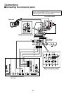
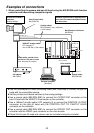
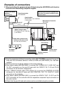
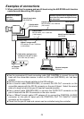
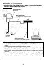
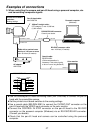
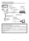
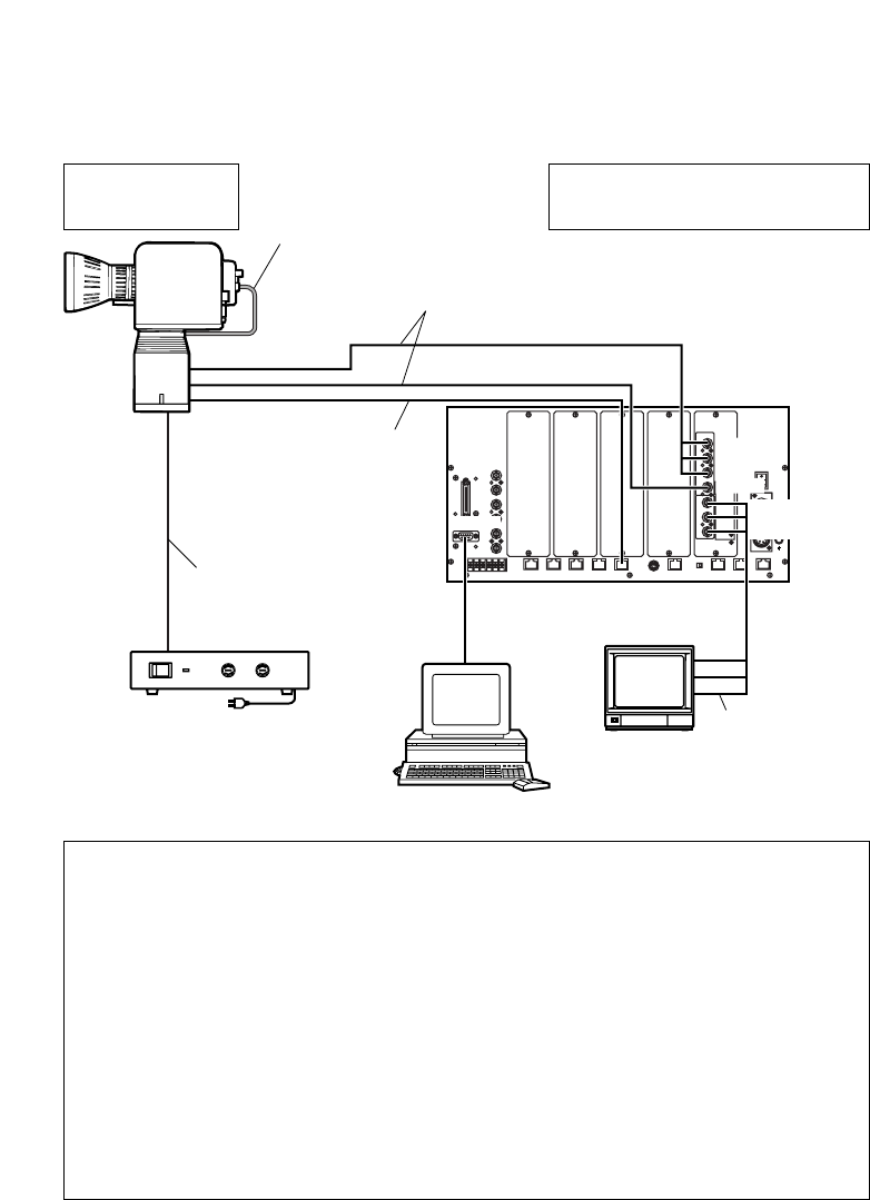
Examples of connections
2. When controlling the camera and pan-tilt head using the AW-RP605 multi-function
controller and transmitting component signals
Color monitor
Pan-tilt head cable:
AW-CA50C29
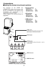
Printed circuit board
switches:
Analog settings
Multi-Function Controller:
AW-RP605
AC adapter:
AW-PS300
Coaxial cables:
BELDEN 8281
Coaxial cables:
BELDEN 8281, max. 3,280 feet
(1,000 meters)
10BaseT straight cable:
UTP category 5, max. 3,280 feet
(1,000 meters)
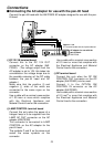
OUse the camera/pan-tilt head connecting cable (AW-CA50C29) to connect the pan-tilt
head with the convertible camera in which an RGB card (AW-PB302), etc. has been
installed.
OSet the printed circuit board switches to the analog settings.
OUse coaxial cables (BELDEN 8281) to connect the Y/VIDEO OUT, Pr/SDI OUT and
Pb OUT connectors on the pan-tilt head with the VIDEO/Y IN, Pr IN and Pb IN
connectors on the controller, respectively.
OUse a 10BaseT straight cable (UTP category 5) to connect the CONTROL IN IP/RP
connector on the pan-tilt head with the CONTROL OUT TO PAN/TILT HEAD
connector on the controller.
OUse coaxial cables (BELDEN 8281) to connect the VIDEO/Y OUT, Pr OUT and Pb
OUT connectors on the controller with the respective component input connectors on
the color monitor.
OCheck that the pan-tilt head and camera can be controlled using the controller.
Cable with a nominal cross
section of 1.25 mm
2
or more
max. 98.4 feet (30 meters)
Personal computer
(Windows)
Genlock signals must be supplied when
more than one camera and pan-tilt head
are to be used.