


14 C2688M-C (12/08)
BASIC HARDWARE CONNECTIONS
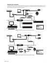
CONNECTING THE MATRIX SYSTEM TO THE EDI5000
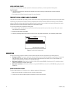
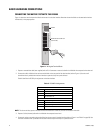
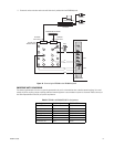
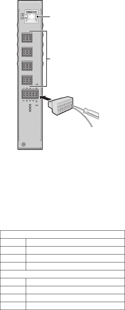
Figure 11 shows how to wire the terminal block and connect it to the data interface. Note that the terminal block can be attached to the data
interface only in the proper position.
Figure 11. Wiring the Terminal Block
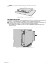
1. Prepare a reversed data cable (user-supplied) with an RJ-45 connector at one end and with the individual wires exposed at the other end.
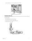
2. Connect the cable’s individual wires to the terminal block on the rear panel of the data interface (refer to Figure 11). Use the small
screwdriver that is provided with the data interface to open the clamp for a particular lead.
Table A identifies the RS-232 pin assignments on the data interface.
NOTE: The alarm and relay inputs on the data interface are reserved for future use, and are not included in this table.
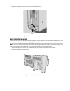
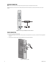
3. Prepare a Cat5e (or better) cable with the individual wires exposed at each end.
4. Connect the wires at one end to the terminal block on the rear panel of the data interface (refer to Figure 11 and Table F on page 39). Use
the small screwdriver that is provided with the data interface to open the clamp for a particular lead.
Table A. RS-232 Pin Assignments
Com 1
Pin Lead
1 RS-232-Data Rx+
5Ground
9 RS-232 Data Tx+
Com 2
Pin Lead
2 RS-232 Data Rx+
6Ground
10 RS-232 Data Tx+
POWER
RESERVED FOR FUTURE USE
(DO NOT USE)