24 C2688M-C (12/08)
Change Serial Port Settings
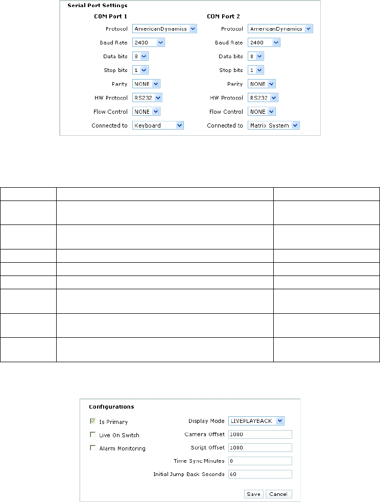
Use the Configuration page in the EDI5000 system configuration software to configure the serial port connection as shown in Figure 24.
Figure 24. EDI5000 Serial Port Settings
Change General Configuration Settings
Figure 25. EDI5000 Configuration Settings
To change the way the EDI5000 operates, modify the following settings:
• Is Primary: This check box is reserved for future use.
• Live On Switch: If you configure the EDI5000 data interface to display both live video and recorded video (by selecting the LIVEPLAYBACK
option; refer to Display Mode below), the Live On Switch setting determines what viewing mode is displayed when an operator switches to
a camera viewed through the data interface. Click this check box to set live video as the default mode. When the check box is cleared, the
monitor defaults to playback mode. In a system where you are using Endura cameras for expansion, it is recommended to set live video as
the default mode. If LIVEPLAYBACK is not selected in the Display Mode box, the Live On Switch setting is ignored.
• Alarm Monitoring: Click this check box to enable the EDI5000 to receive alarms from the Endura system. When configuring alarms in the
Endura system, be sure to assign each alarm a unique logical number. Configure a matrix system alarm for each alarm received from the
Endura system, using physical numbers for the matrix alarms that match the logical numbers used in the Endura system. Refer to the
Setting Description Value
Protocol Select the communication protocol that matches the
manufacturer of the matrix system
AmericanDynamics
Baud Rate Baud rate Use the same baud rate used
for the matrix system
Data bits Data bits 8
Stop bits Stop bits 1
Parity Parity None
HW Protocol This is the serial communication interface used for
communication between devices
RS-232
Flow Control This setting controls the rate of data transmission between
devices; use the default
None
Connected to This setting must correspond to the actual wiring connections
between the data interface and the matrix system components
COM Port 1: Keyboard
COM Port 2: Matrix System


