


SYSTEM BASICS
Selecting and Displaying Windows–Serial Port Control
10 SuperView 3000 User Manual May 9, 2002
3
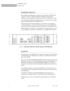
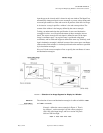
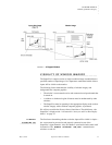
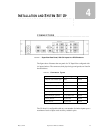
Example––define the destination rectangle in Figure 4. That
is, place the top left corner of window 1 at (300, 700) of the
display’s raster, and use a window 600 pixels wide and 250
lines high:
>wdr 1 300 700 600 250
The SuperView provides query commands that let you get the current value(s)
of most system parameters.
Example––query the SuperView on the current WDR values
for window 1:
>wdr 1
The system responds by listing the frame buffer coordinate
values:
>300 700 600 250
.
............
ASPECT RATIO
Any desired rectangular portion of an input image can be displayed in the
corresponding window. Also, the window itself can be set to have any
rectangular shape and be any desired size on the monitor, up to the full size of
the output raster. The size and shape of the source rectangle are independent of
the destination rectangle’s size and shape. This has important consequences.
Let us suppose that you defined an input’s source and destination rectangles so
that the central 320 pixels by 240 lines of a video source image were mapped
into a 640x480 window. In this case, the destination rectangle is larger than the
source rectangle, but has the same shape and the same width-to-height aspect
ratio (4:3). Thus, the original input image is scaled equally in both dimensions
for display on the monitor.
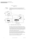
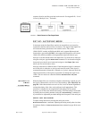
Varying the destination rectangle’s size but preserving its aspect ratio makes the
displayed image larger or smaller. As long as its proportions correspond to
those of the source rectangle, the displayed image will resemble the input
image. If you independently vary the shape of either the source or destination
rectangle, so that their aspect ratios are no longer the same, your displayed
picture will appear stretched or squeezed compared to the original image.
Figure 4 shows how the image is stretched by using a destination rectangle with
a different, more elongated shape than that of the source rectangle.
POSITIONING
.
............
AND CLIPPING
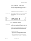
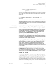
A window can be positioned anywhere on the output raster. If the window’s
destination rectangle is defined so that a portion of the window is off the screen,
that portion of the windowed image is clipped (until it is moved back into
view). This “image clipping” is illustrated in Figure 5. The window is
positioned by specifying the screen coordinates of its top left corner. Negative
coordinate values clip from the left and top edges of the window.