


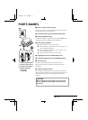
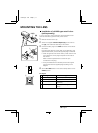

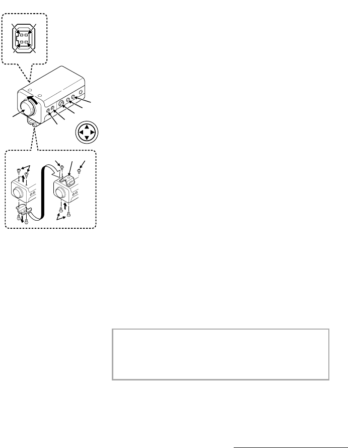
PARTS NAMES
1 Lens iris output connector (4 pin)
This 4-pin connector is used to send the DC control signal and
power supply to an auto-iris type lens.
2 Auto white balance push lock button (AWB LOCK)
3 Menu setting button (SET)
Connect the camera to the monitor, then press the SET button
for about 3 seconds to display the on-screen menu.
4 Cursor button (CURSOR)
j: Press this button to move the cursor up.
c: Press this button to move the cursor to the right, or to
turn the settings ON/OFF etc.
d: Press this button to move the cursor to the left, or to
turn the settings ON/OFF.
l: Press this button to move the cursor down.
5 Flange-back lock screw (FLANGE BACK LOCK)
6 Flange-back adjustment screw (FLANGE BACK ADJ.)
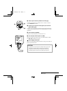
7 Lens mount cap
The cap is installed to protect the lens mount section.
Remove the lens mount cap before installing a lens (sold
separately).
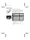
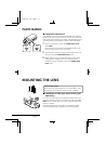
8 Camera installation bracket
The bracket can be fixed at the top or bottom of the camera.
When fixing the bracket, be sure to use the longer screws and
install the shorter screws on the opposite side to seal the
openings.
CAUTION:
When installing the camera support, select a location
that can support the total weight of the camera and
accessories.
1
2
3
2
1
8
7
4
3
2
1
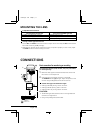
4
1
2
3
5
6
1 Shorter screws: M3 x 4
2 Longer screws: M3 x 6
3 Camera mounting
screw hole:
1/4"-20 UNC
L53P4/US GB 1998, 3, 11
4 English