


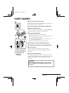
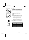

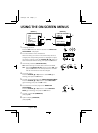

F Video output connector (VIDEO OUT: BNC type)
Connect this connector to a device such as a VCR or monitor
with a VIDEO IN connector.
G External sync composite video signal input connector
(VBS IN: BNC type)
Connect to this connector the synchronizing signal output from
a synchronizing signal device or the composite signal of a video
distributor.
H Power indicator (POWER)
Comes on when the power to the camera is on.
I 24 V AC input terminal (24 V AC, GND)
With this camera use only the 24 V AC power adaptor model
No. VPT-115 available from Sanyo.
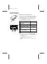
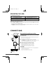
Power supply connections
Use a 3 wire grounded cable (22 AWG or more), and connect as
shown by the illustration.
CAUTION:
• To prevent camera and/or AC adaptor failure, pay close
attention to polarity when making the connections.
• To prevent fire hazard any UL listed wire rated VW-1,
should be used for the 24 V AC cable input terminal.
F
H
I
G
GND
AC
AC
L53P4/US GB 1998, 3, 11
6 English