


11
Installation
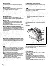
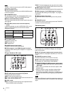
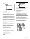
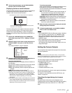
When the DISPLAY/MENU switch is set to DISPLAY
Items set to ON using the menu or related switches will be
displayed.
a TALK indication
Displayed when the intercom microphone is set to ON.
b EX (lens extender) indication
Displayed when a lens extender is in use.
c Zoom position indication
Indicates the approximate position of the zoom lens variator
between wide angle (0) and telephoto (99).
d Battery voltage indication
When the CAMERA POWER switch is set to EXT, the DC IN
voltage is displayed.
When the switch is set to CCU, the internal voltage of the
camera is displayed.
e Focus position indication
Shows the focus position of a zoom lens as a numeric value (0
to 255 [infinity]).
f 5600K mode indication
Displayed when the internal electrical filter (5600K) is set to
ON.
g Filter indication
Displays the type of ND filter currently selected with a number
(1, 2, 3, or 4).
h White balance memory indication
Shows the currently selected white balance automatic
adjustment memory. This is not displayed when a CCU is
connected.
W:A: The WHITE BAL switch is set to A.
W:B: The WHITE BAL switch is set to B.
W:P: The WHITE BAL switch is set to PRST.
i Gain value indication
Shows the video gain value (dB) set with the GAIN switch.
j Shutter/ECS indication
Displays the shutter/ECS status. Nothing is displayed if the
electronic shutter is set to OFF.
k F-value indication
Indicates the lens F (iris opening) value.
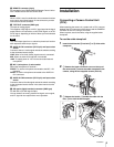
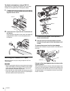
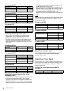
When the STATUS/CANCEL switch is set to
STATUS
The status display is changed to show the following items:
a Assignable button indication
The functions assigned to the assignable buttons are
indicated.
For the functions that can be assigned, see OPERATION
menu <SWITCH ASSIGN1> (page 26).
b Format indication
The current video format is displayed.
c ‘!’ indication area
This area is used to display abnormal statuses, using the ‘!’
IND function. Display options can be set, using the menu.
For details, see OPERATION menu <‘!’ IND> (page 25).
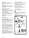
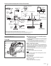
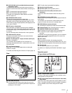
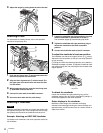
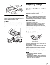
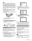
Attaching a Microphone
A microphone can be attached to the camera, using the
microphone holder of the viewfinder or an optional CAC-12
Microphone Holder.
For attaching to the microphone holder of the viewfinder, refer
to the instruction manual for the viewfinder.
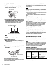
When the microphone is attached to the
microphone holder of the viewfinder
Secure the microphone cable A to the cable clamp B of the
camera.
F255
12.5V
EX Z55
1 A
F5.6
0dB 1/125
W:
5600
TALK
1
2
3
45
6
7
8
9
0
qa
3
12
FORMAT :1080-59.94i
ASSIGNABLE1 :5600K
ASSIGNABLE2 :OFF
ASSIGNABLE REAR:OFF
!ND :2
!FAN :MAX
!EXT :ON
!FORMAT :1080-59.94i
O
F
F
O
N
S
E
L
W
H
T
B
L
K
S
H
U
T
T
E
R
R
E
T
L
E
N
S
I
N
E
T
E
R
C
O
M
L
E
V
E
L
M
IC
V
F
A
B